Multiple internal shield termination system

a termination system and shield technology, applied in the direction of cable termination, cable junction, coupling device connection, etc., can solve the problems of no adequate structure to attach the ground, time-consuming methods, and low resistance of backshell, so as to reduce the conductive material and reduce the resistance

Inactive Publication Date: 2002-01-15
ICORE INT
View PDF14 Cites 25 Cited by
  • Summary
  • Abstract
  • Description
  • Claims
  • Application Information

AI Technical Summary

Benefits of technology

It is an object of the present invention to provide a low resistance shield termination system that allows a backshell to be constructed of less conductive material than previously whil

Problems solved by technology

These methods are time consuming to install or repair and are generally hampered by the lack of access to the wires within the backshell.
In many instances, there is no adequate means within the structure to attach the ground leads to the backshell so as to be close to the mating connector interface.
Further, these methods rely on the conductivity of the backshell and are unsuitable for applications requiring a low conductivity, or non-conductive backshell material; examples include lightweight plastics or corrosion resistance stainless steel, not good conductors or shields.
If the attachment of leads takes place outside of the protec

Method used


Image

  • Multiple internal shield termination system
  • Multiple internal shield termination system
  • Multiple internal shield termination system

Examples


Embodiment Construction

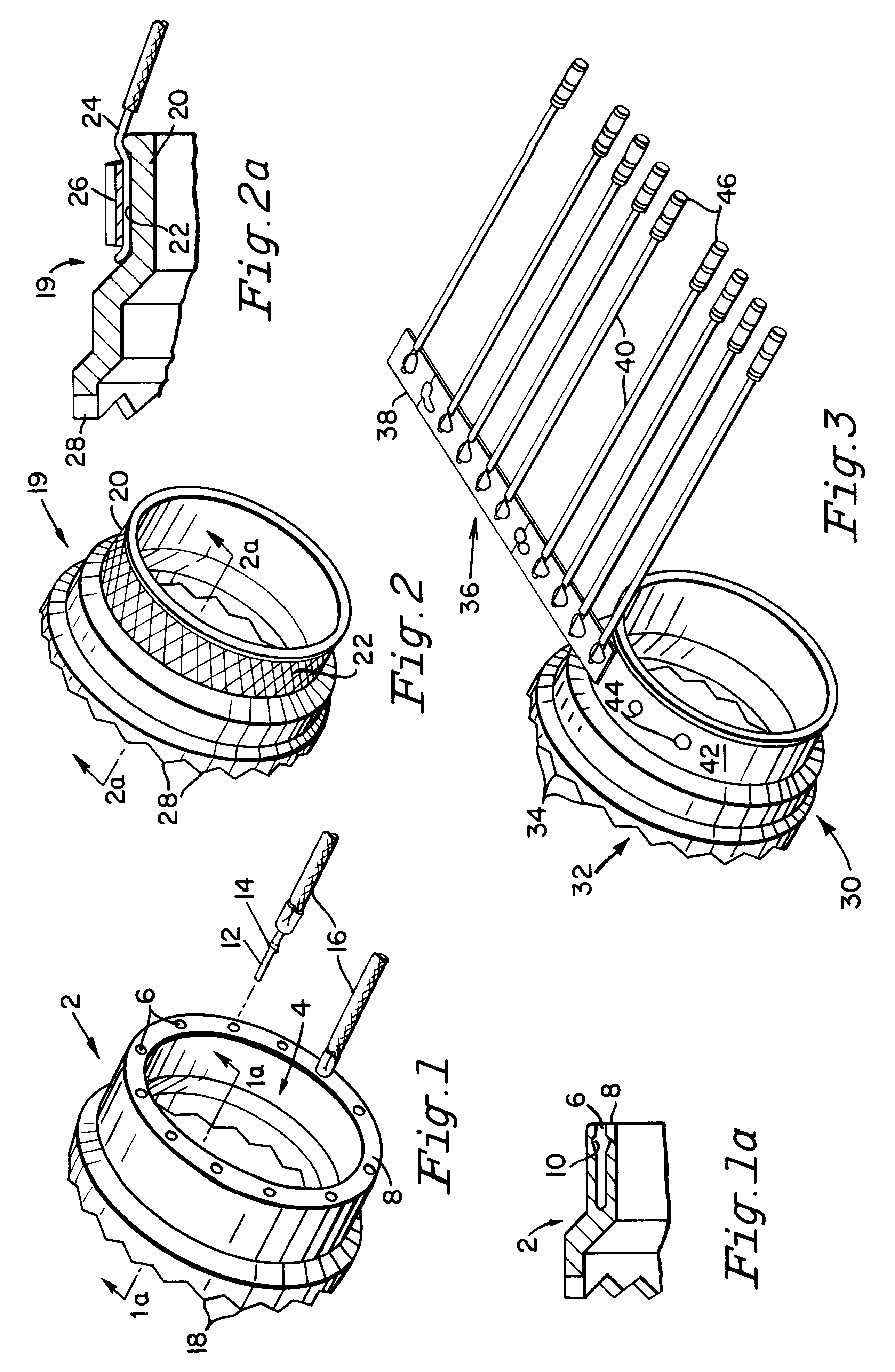
Referring now specifically to FIG. 1 of the present invention, there is illustrated one form of yoke of the invention generally designated by the reference numeral 2. The yoke is an annulus having a large center opening 4 and in this configuration a plurality of apertures 6 formed in a rear wall 8 of the yoke 2; the wall 8 being transverse to the axis of the annulus. The apertures 8 have indents (or notches) 10 that cooperate with ridge 12 on pins 14 secured to the ends of conductors 16 to be terminated in (grounded at) the yoke 2. The conductors 16 are the braids of the individual cable conductors and the grounding wires for the cable braid.

The front of the yoke 2 has teeth 18 to engage teeth conventionally found on the back of a multipin connector, see FIG. 6 teeth 126.

The yoke may be a lightweight metal such as aluminum, a lightweight plastic with metalized coating or a lightweight plastic with metallic inserts to provide continuity from the grounding leads to a connector.

Referri...


PUM


Abstract

A conductive yoke is provided insertable into a backshell adapter to provide a convenient shielding termination system for grounding braids and shields of conductors in a multiconductor cable to be connected to and grounded at a multipin electrical connector, the yoke providing ease of connection of such braids and shields to it and having direct electrical contact to the grounded surface of the connector.

Description

FIELD OF THE INVENTIONThe present invention relates to electrical grounding of shielded cables and wires to a connector housing, and more particularly to an improved backshell adapter with an easily removable interface yoke suitable for attaching cable shields and grounding leads through a low resistance path directly to the connector housing.BACKGROUND OF THE INVENTIONElectrical connectors coupled to a cable by way of a backshell adapter provide reliable means for attaching a cable to an electrical component. The backshell adapter secures the cable to the connector while the connector provides a releasable means for transmitting the cable signals across a junction. This arrangement is of particular value for sophisticated electronics equipment requiring multiple wires transmitting signals and power to external components. Such equipment is often found in aircraft, satellites, military vehicles, electronically controlled machinery, and similar equipment.Wires in the cables of sensit...

Claims


Application Information

Patent Timeline
IPC IPC(8): H01R9/05H01R9/03H01R13/516H01R13/658H01R13/6593
CPCH01R9/038H01R9/0512H01R13/6593H01R13/516H01R13/65918
Inventor GOETT, EDWARD P.WOEHL, ROGERSPRATT, ROBERT F.
Owner ICORE INT
Why Eureka
Try Eureka