Antenna array calibration

a technology for antenna arrays and antenna beams, applied in the direction of antennas, instruments, electrical equipment, etc., can solve the problems of antenna beam shape and antenna beam direction errors, and achieve the effect of improving the performance of the radio communication system, increasing the beam shape accuracy, and being easy to us

Inactive Publication Date: 2002-01-15
TELEFON AB LM ERICSSON (PUBL)
View PDF3 Cites 223 Cited by
  • Summary
  • Abstract
  • Description
  • Claims
  • Application Information

AI Technical Summary

Benefits of technology

Another problem dealt with by the present invention is how the calibration of an antenna array used in a cellular communication system can be accomplished in an easy and cost efficient way, essentially without disturbing the normal traffic in the communication system.
It is an object of the present invention to improve the performance of the radio communication system by increasing the accuracy of the beam shape and direction of the antenna beam.
It is another object of the present invention to calibrate an antenna array used in a cellular communication system essentially without disturbing the traffic in the communication system, in an easy and cost efficient way.
In another embodiment of the calibration of an antenna array that transmits communication signals a set of different orthogonal calibration signals is generated by the calibration controller and the calibration could then be performed simultaneously for all of the transmitting antenna sections. An advantage with the present invention is that the performance of a radio communication system is improved by increasing the accuracy of the beam shape and direction of the antenna beam.
Another advantage is that an antenna array in a cellular communication system is calibrated essentially without disturbing the traffic in the communication system, in an easy and cost efficient way.

Problems solved by technology

These errors affect the beam shape and the direction of the antenna beam.

Method used


Image

  • Antenna array calibration
  • Antenna array calibration
  • Antenna array calibration

Examples


first embodiment

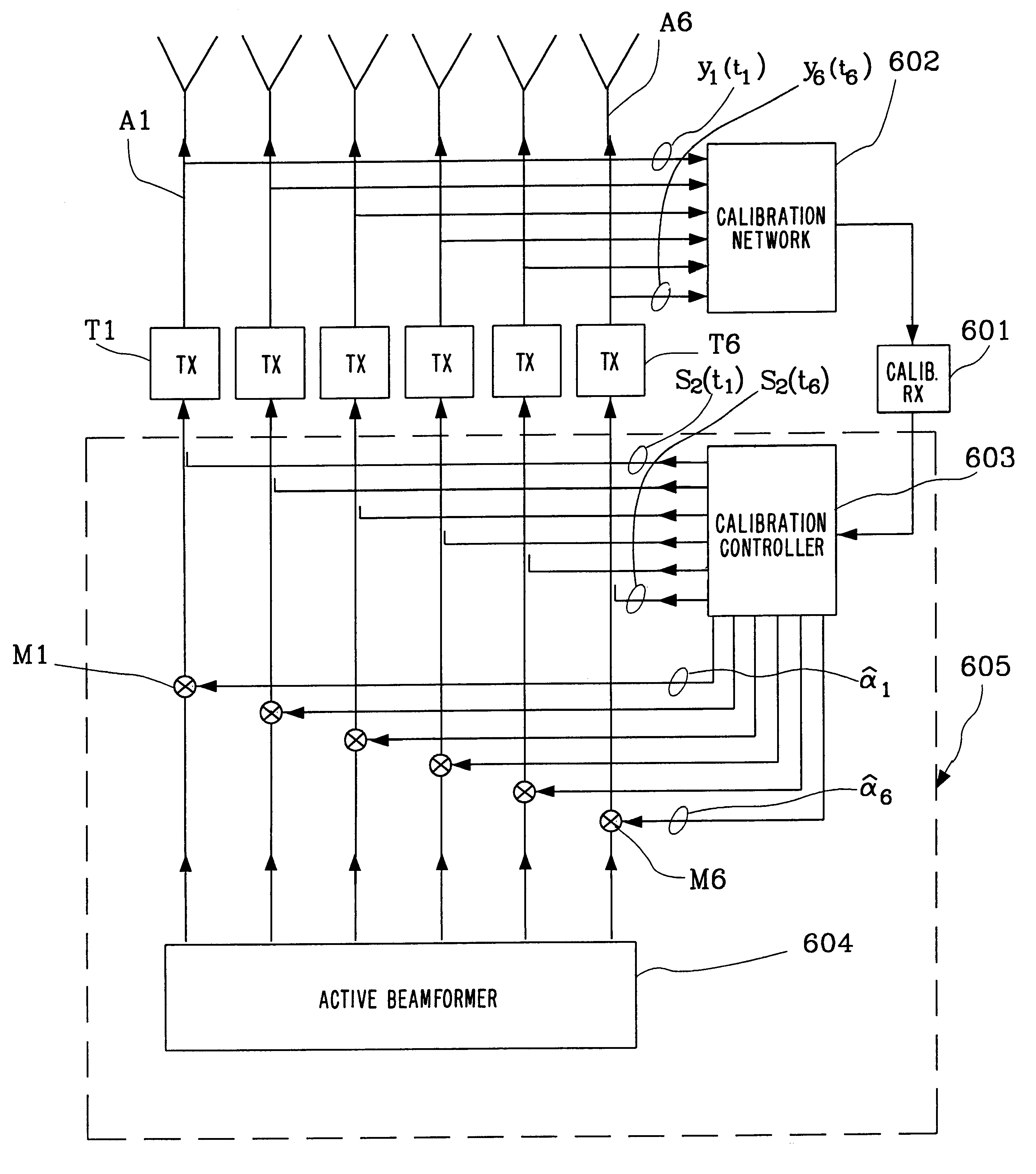
In the transmission calibration the same calibration signal is used for calibrating all transmitting antenna sections. This means that the calibration controller comprises only one signal generator. If all transmitting antenna sections were to send the same signal simultaneously the single calibration receiver would interpret the sampled data as one signal and therefore not be able to distinguish data from separate transmitting antenna sections. Hence each of the transmitting antenna sections has to be calibrated separately in time in this example.

The calibration signal S2(t.sub.1) is first injected into a first, reference, transmitting antenna section A1 at a first time t.sub.1. The calibration network 602 samples this transmitting antenna section when the calibration signal has passed the transmitting components T1. The distorted signal y1(t.sub.1) is received at a first collection time by the calibration receiver 601.

Thereafter the same calibration signal S2(t.sub.2) is injected ...

second embodiment

In the calibration of an antenna array in a FDMA-system, according to option b), free frequencies are used for a short period of time, for example the time between the termination of a call on a certain frequency and the set up of another call using that frequency.

third embodiment

In the calibration of an antenna array in a FDMA-system, according to option c), a low-power spread spectrum signal is superimposed on top of a specific carrier.

The present invention severely reduces the accuracies required of the components connected to each antenna section because the present invention measures and corrects for errors generated by these components. In addition, the system used for calibration simultaneously tests the devices associated with each antenna section so as to verify that the antenna array is working properly.

The invention provides a method and apparatus for calibrating the antenna sections of an antenna array comprised in a base station. The calibration can be performed essentially without interrupting or disturbing the normal traffic flow in the radio communication system. The calibration apparatus according to the invention only comprises one single calibration transmitter and one single calibration receiver, used to calibrate the whole receiving and ...


PUM


Abstract

A method and a system for calibrating the reception and transmission of an antenna array for use in a cellular communication system is disclosed. The calibration of the reception of the antenna array is performed by injecting a single calibration signal into each of a number of receiving antenna sections, in parallel. The signals are collected after having passed receiving components that might have distorted the phase and amplitude. Correction factors are generated and applied to received signals. The calibration of the transmission of the antenna array is preformed in a similar way. A single calibration signal is generated and injected into each of a number of transmitting antenna sections, one at a time. The signals are collected, one at a time, after having passed transmitting components that might have distorted the phase and amplitude. Correction factors are generated and applied to signals that are to be transmitted.

Description

The cellular industry has made phenomenal strides in commercial operations in the United States as well as the rest of the world. The number of cellular users in major metropolitan areas has -far exceeded expectations and is outstripping system capacity. Innovative solutions are thus required to meet these increasing capacity needs as well as to maintain high quality service and avoid raising prices. Furthermore, as the number of cellular users increases, the problems associated with cochannel interference become of increased importance.FIG. 1 illustrates ten cells C1-C10 in a typical cellular mobile radio communication system. Normally, a cellular mobile radio system would be implemented with more than ten cells. However, for the purposes of simplicity, the present invention can be explained using the simplified representation illustrated in FIG. 1. For each cell, C1-C10, there is a base station B1-B10 with the same reference number as the corresponding cell. FIG. 1 illustrates the...

Claims


Application Information

Patent Timeline
Patent Type & Authority Patents(United States)
IPC IPC(8): H01Q3/26
CPCH01Q3/267
Inventor ANDERSSON, SORENFORSSEN, ULFOVESJO, FREDRIK BENGTPETERSSON, SVEN OSCAR
Owner TELEFON AB LM ERICSSON (PUBL)
Why Eureka
Try Eureka