Gold coated signal cable

a signal cable and gold coating technology, applied in the direction of instruments, fibre mechanical structures, optics, etc., can solve the problems of general increase in loss, attenuation of light being transmitted, and vulnerable cables

Inactive Publication Date: 2002-01-29
OPTOPLAN
View PDF9 Cites 31 Cited by
  • Summary
  • Abstract
  • Description
  • Claims
  • Application Information

AI Technical Summary

Benefits of technology

Another object of the invention is to provide such a device which also reduces the formation of hydrogen in the area around the fibre optical cable in oil / gas wells.

Problems solved by technology

In addition, the cables are vulnerable to corrosion because they are usually located in the liquid filled annulus between the casing and the tubing.
The hydrogen diffuses into the optical fibre and results in attenuation of the light being transmitted.
Permanent losses are a result of a reaction between the hydrogen which diffuses into the optical fibre, and the silica glass, and the loss will generally increase with the hydrogen concentration, and with time.
Because of the high temperature prevailing in such wells, normally 100-200.degree. C., the hydrogen will quickly penetrate into a steel tube which encapsulates the fibre, and diffuse into the optical fibre and cause losses.
Even at much lower hydrogen pressures, the loss in the fibre will normally be so high that the cable is no longer usable for the intended purpose.
The use of copper in such applications is, however, not practical, because of the high hydrostatic pressure to which the cable is exposed.
Copper will further not be a particularly effective barrier against hydrogen at the high temperatures of interest.
Secondly, the solubility of hydrogen in gold is very low, and therefore the permeability rate for hydrogen in gold is very low.
A gold coating on the interior surface will only produce a barrier effect and besides be harder to apply than an exterior coating.

Method used


Image

  • Gold coated signal cable
  • Gold coated signal cable

Examples


Embodiment Construction

This calculation example is put forward in order to illustrate the barrier effect of gold, with a coating thickness of 3 micrometers as a function of temperature and time, in comparison with an unprotected steel tube.

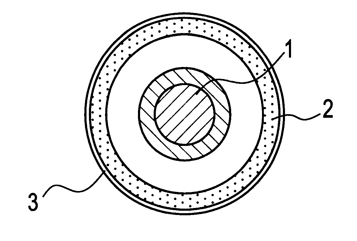
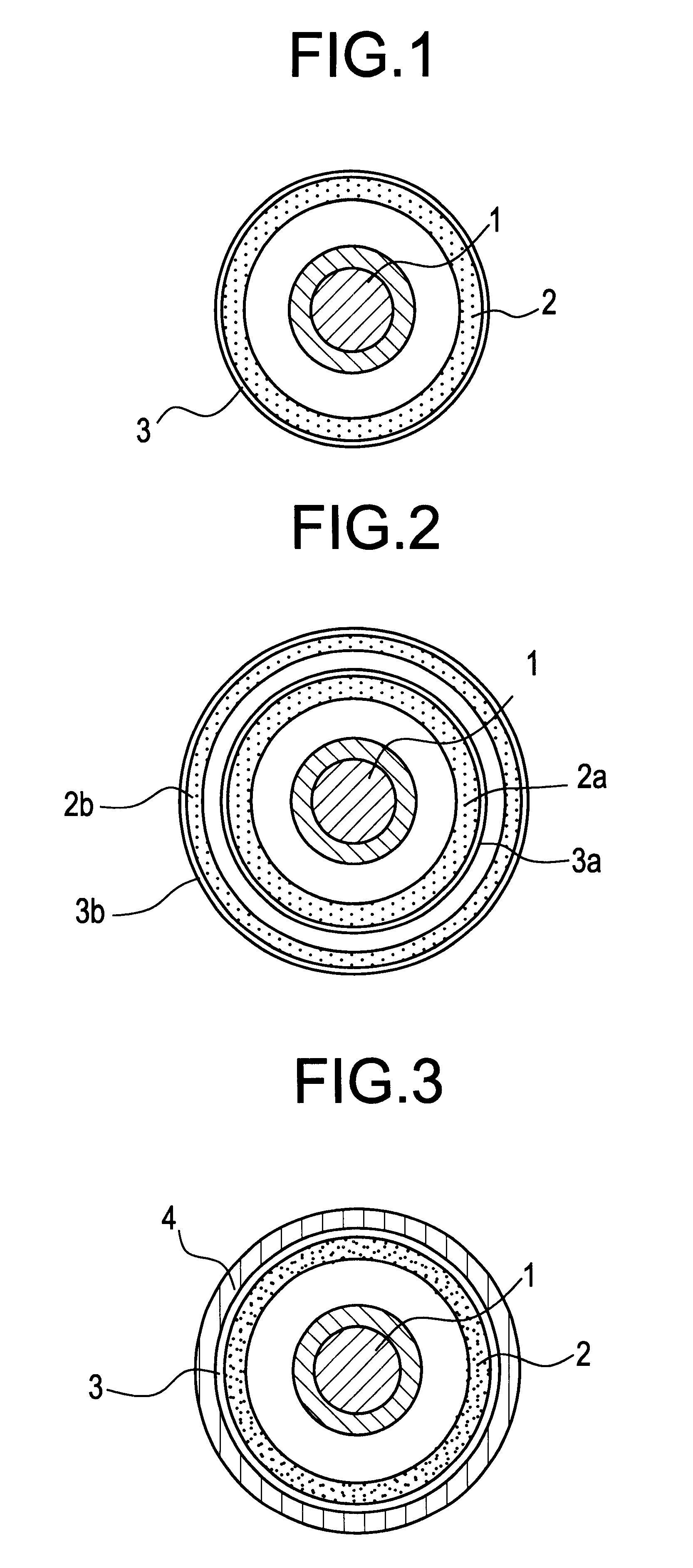
The table which is given below, presents the calculation results for an unprotected steel tube (Inconel 625) and a steel tube provided with a 3 micrometers thick gold coating after 1 and 5 years, at a partial pressure of hydrogen at 1 and 100 atmospheres at 100 and 200.degree. C. It is assumed that the steel tube has an outer diameter of 1.8 mm, and an inner diameter of 1.4 mm. These are realistic dimensions for most applications. The hydrogen permeability for gold is about 1.multidot.10.sup.-4 exp(-15840 / T)mol / cm sec. atm. The hydrogen permeability for Inconel 625 is about 8.16.multidot.10.sup.-7 exp(-7232 / T)mol / cm sec. atm. T is the absolute temperature in K.

As can be seen from the table, a gold-coating of 3 .mu.m produces a substantial reduction of the hydrogen press...


PUM


Abstract

Signal cable for transmission of optical signals, especially in oil and gas wells, includes at least one elongated optical fiber, and an elongated, generally tubular container within which the optical fiber is disposed, the container having an inner wall and an outer wall, a space being defined between the optical fiber and the inner wall. At least one of the inner wall and the outer wall has a thin continuous surface coating of gold or a gold alloy.

Description

The invention relates to a signal cable for transmission of optical signals in oil and gas wells.DESCRIPTION OF RELATED ARTSignal cables are i.a. used in oil and gas wells for measurement of such parameters as pressure, temperature, tension, flow, and for fibre optic communication. The cables may have a length of 6 km or more for use in wells, and should tolerate temperatures of 200.degree. C. and pressure over 1000 bar. In addition, the cables are vulnerable to corrosion because they are usually located in the liquid filled annulus between the casing and the tubing.NO patent-publication 175119 describes a cable for this application, where the fibre is inside a steel tube which protects it from the hydrostatic pressure which normally will be several hundred bar. The tube is stranded around a centre element, and the fibre is able to move sidewise in the tube so that some elongation of the cable due to thermal expansion and / or mechanical tension, is possible without straining the fibr...

Claims


Application Information

Patent Timeline
Patent Type & Authority Patents(United States)
IPC IPC(8): G02B6/44
CPCG02B6/4402G02B6/44382
Inventor HORDVIK, AUDUNERIKSRUD, MORTEN
Owner OPTOPLAN
Why Eureka
Try Eureka