

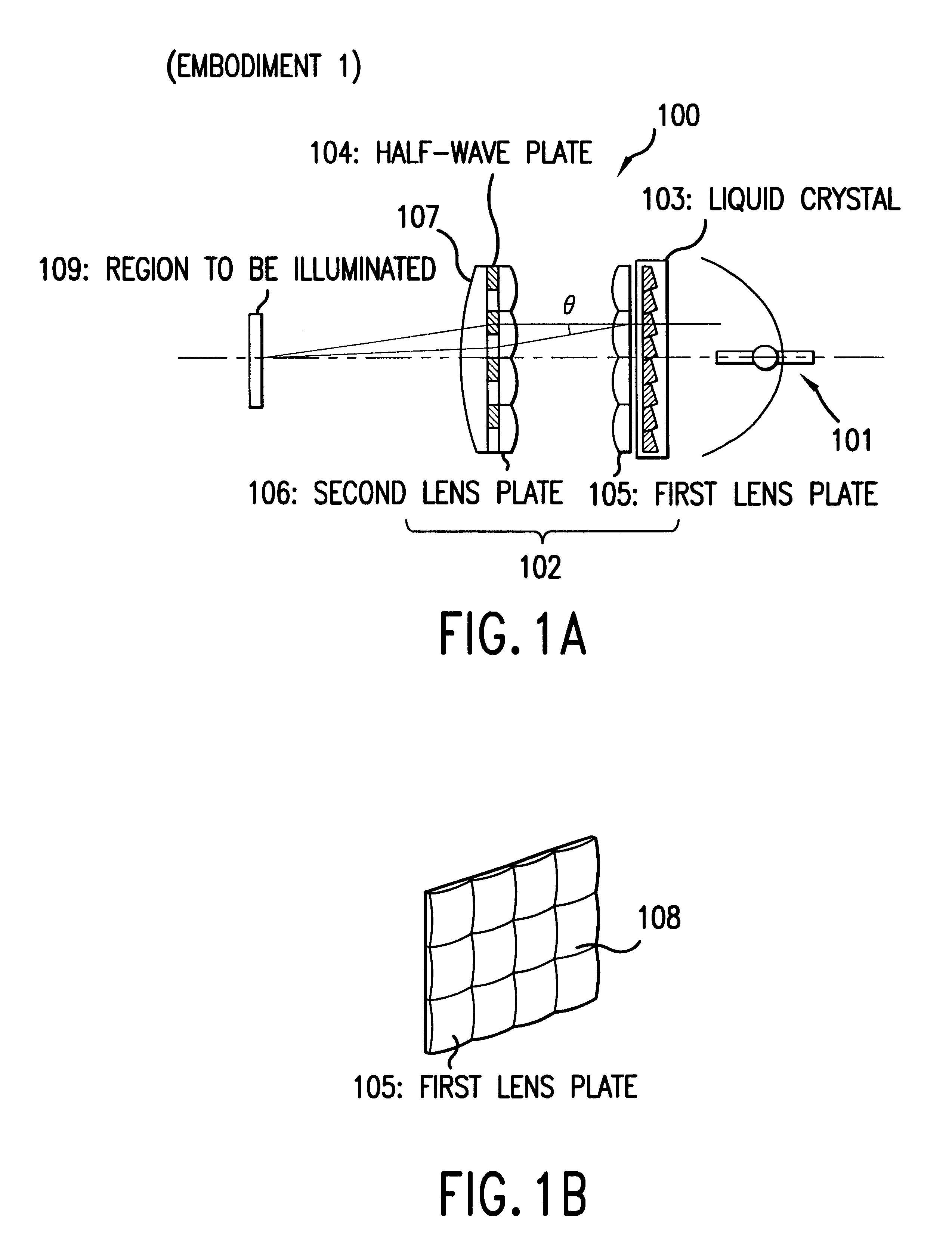
Polarization luminaire and projection display
a technology of projection display and polarizing luminaire, which is applied in the direction of polarising elements, lighting and heating apparatus, instruments, etc., can solve the problems of inconsistencies in colors, the angle of output light is liable to vary, and the optical system is riven
- Summary
- Abstract
- Description
- Claims
- Application Information
AI Technical Summary
Benefits of technology
Problems solved by technology
Method used
Image

Examples
embodiment 10
Incidentally, Embodiment 10 is in a condition in which the width of each of the small lenses 44 of the first lens plate 441 is equal to that of each of the quadrangular prisms composite elements 1205A to 1205E. Namely, assuming that the width W1 of each of the prism composite elements 1205A to 1205E is expressed as (1 / n) times the width W2 of each of the rectangular lenses 443 of the first lens plate 441 where n is an integer equal to or more than 1, such a condition is equivalent to the condition that n is equal to 1. As n is gradually increased to 2,3, . . . , the width of each of the prism composite elements 1205A to 1205E is decreased. Thus, the thickness of each of the prism composite elements 1205A to 1205E can be reduced.
For example, when n is set at 2, the polarized light splitting portion 1201 of the polarization luminaire 1250 becomes configured as illustrated in FIG. 13. Namely, the width W1 of each of the square-pole-like prism composite elements 1205A, 1205B, 1205C, . ....
embodiment 11
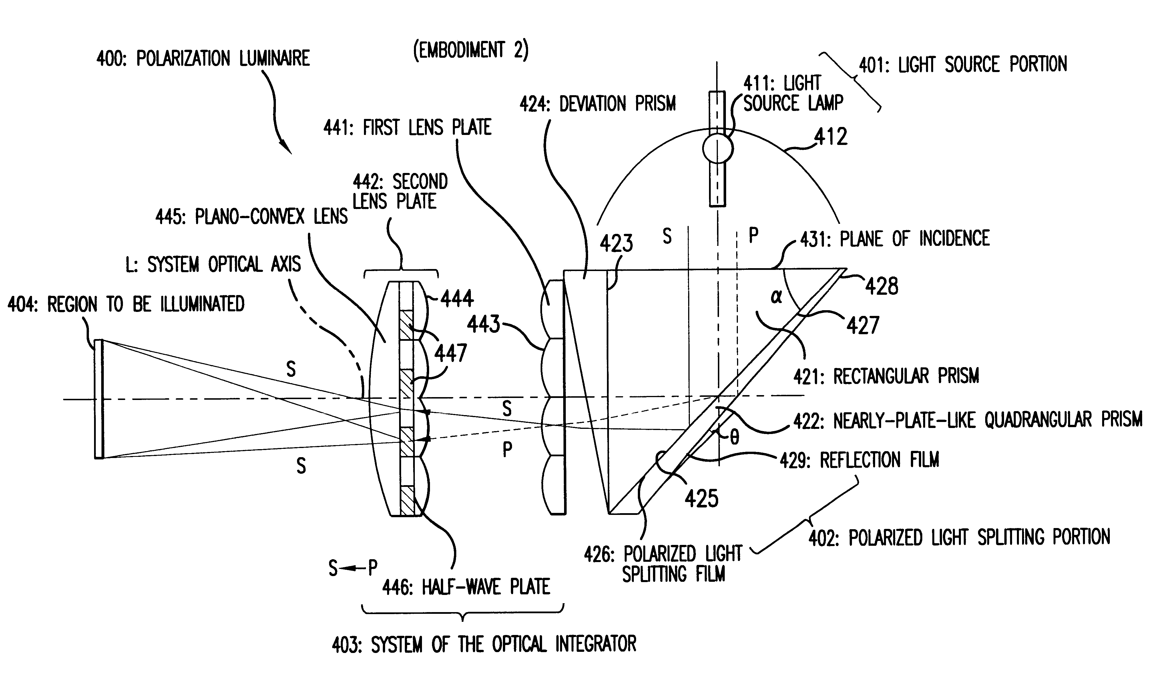
FIG. 14 is a schematic diagram for schematically illustrating a plan view of a primary part of a polarization luminaire of Embodiment 11. Similarly as in the case of the polarization luminaire of Embodiment 2, the polarization luminaire 1400 of this embodiment has a light source portion 401, a polarized light splitting portion 1401 and a system of the optical integrator 403, which are placed along a system optical axis L. This luminaire is established in such a manner that light radiated from the light source portion 401 reaches a rectangular region 404 to be illuminated, through the polarized light splitting portion 1401 and the system of the optical integrator 403. Incidentally, the light source portion 401 faces the rectangular region 404 to be illuminated, and the entire system optical axis L is shaped like a straight line.
embodiment 2
Similarly as in the case of Embodiment 2, the light source portion 401 is established in such a manner that randomly-polarized lights radiated from the light source lamp 411 are reflected by a paraboloidal reflector 412 in a single direction and thus become a nearly parallel luminous flux that are then incident on the polarized light splitting portion 1401.
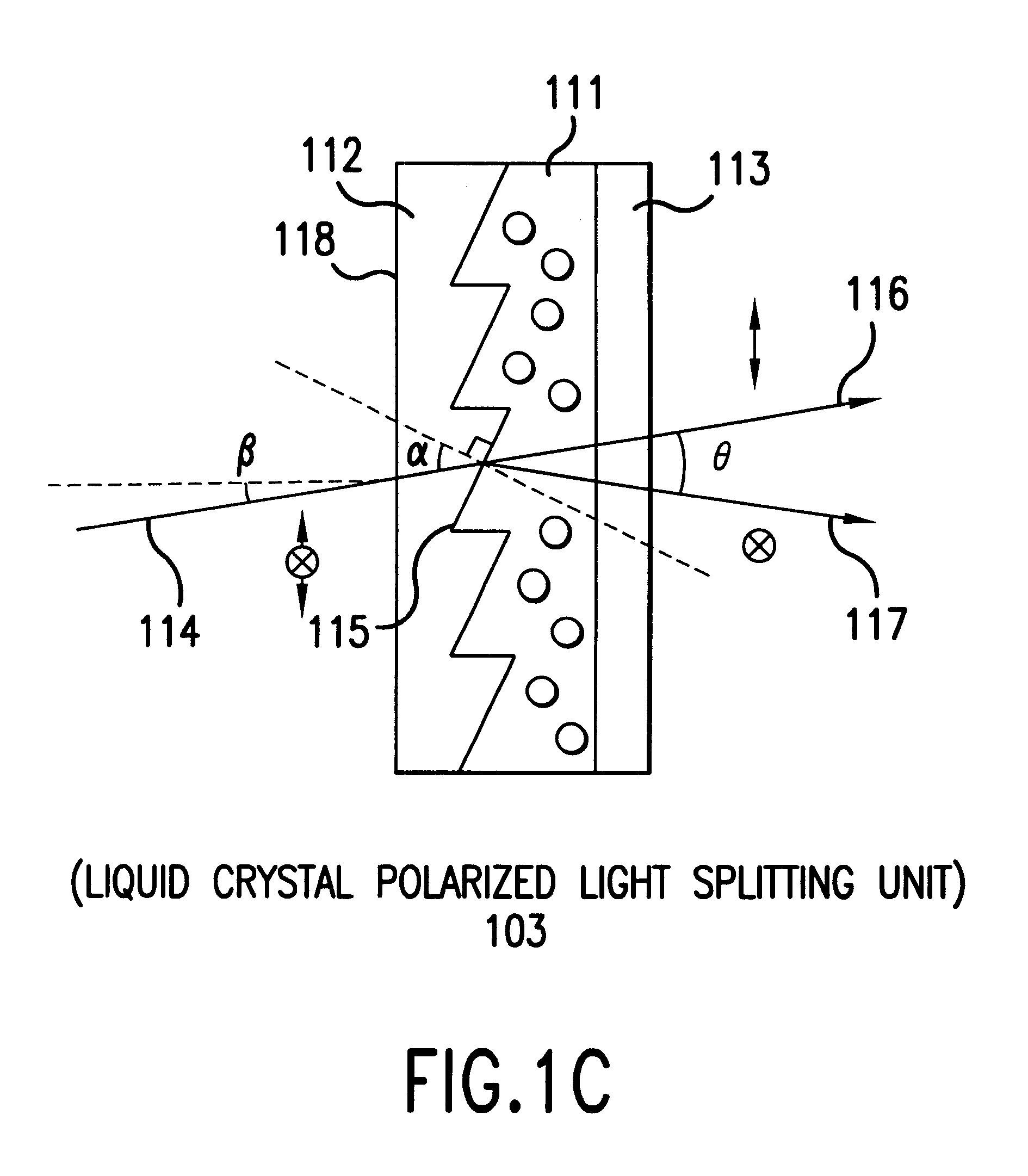
The polarized light splitting portion 1401 is composed of square-pole-like prism composite elements 1404A, 1404B, 1404C and 1404D, each of which comprises first and second rectangular prisms 1402 and 1403 (namely, triangular prisms).
In the case of each of the prism composite elements 1404A to 1404E, the polarized light splitting film 426 is formed on an inclined surface portion 1411 of the first rectangular prism 1402. The inclined surface portion 1412 of the second rectangular prism 1403 is bonded to the inclined surface portion 1411 of the first rectangular prism 1402 in such a way that the polarized light splitting film 426 is ...
PUM
| Property | Measurement | Unit |
|---|---|---|
| angle | aaaaa | aaaaa |
| deviation angle | aaaaa | aaaaa |
| refractive index | aaaaa | aaaaa |
Abstract
Description
Claims
Application Information