Clutch engaging and disengaging apparatus

a technology of engaging and disengaging apparatus, which is applied in the direction of fluid actuating clutches, non-mechanical actuated clutches, clutches, etc., can solve the problems of occupying a lot of time, contributing to the cost of the slave cylinder and piston unit, and the cost of the entire clutch actuating apparatus, etc., and achieves deformation resistance and is easy to deform

Inactive Publication Date: 2002-02-12
SCHAEFFLER TECH AG & CO KG
View PDF17 Cites 8 Cited by
  • Summary
  • Abstract
  • Description
  • Claims
  • Application Information

AI Technical Summary

Benefits of technology

Another object of the invention is to provide a cylinder and piston unit which can be utilized with advantage as a central slave cylinder and piston unit in the system for actuating the friction clutch of the power train in a motor vehicle.
A further object of the invention is to provide a compact, relatively inexpensive, deformation-resistant and hence long-lasting cylinder and piston unit for use in a clutch engaging / disengaging apparatus.

Problems solved by technology

The assembly of the cylinder with the separately produced sleeve-like guide and with the separately produced extension takes up much time and such constituents of the apparatus must be produced and shaped in separate machines or production lines.
All this contributes considerably to the cost of the slave cylinder and piston unit and of the entire clutch actuating apparatus as well as to the cost of the power train.
Furthermore, the weight of the fully assembled unit including the steel cylinder, the steel guide and the steel extension is quite pronounced.
Moreover, the assembled combination of cylinder, guide and extension embodies two potential weakened zones which are prone to leakage, namely one between the interconnected end portions of the cylinder and the guide, and the other between the cylinder and the extension.
Still further, the one-piece thermosetting cylinder exhibits the tendency to undergo highly pronounced thermally induced expansion which affects the quality of the sealing action between such cylinder and the piston of the slave unit; this can be counteracted by resorting to a complex and hence bulky and highly expensive sealing arrangement between the cylinder and the piston.

Method used


Image

  • Clutch engaging and disengaging apparatus
  • Clutch engaging and disengaging apparatus
  • Clutch engaging and disengaging apparatus

Examples


Embodiment Construction

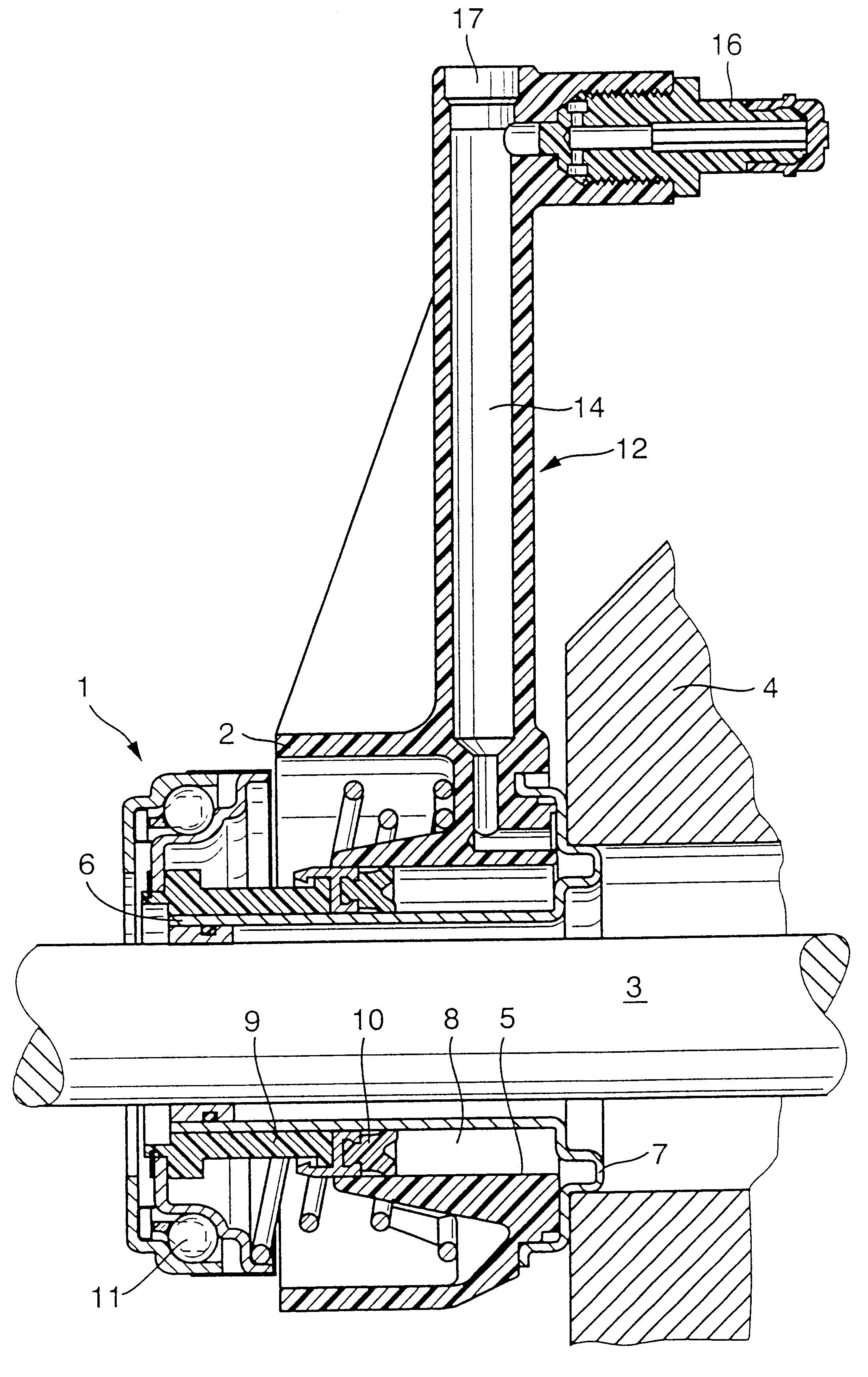
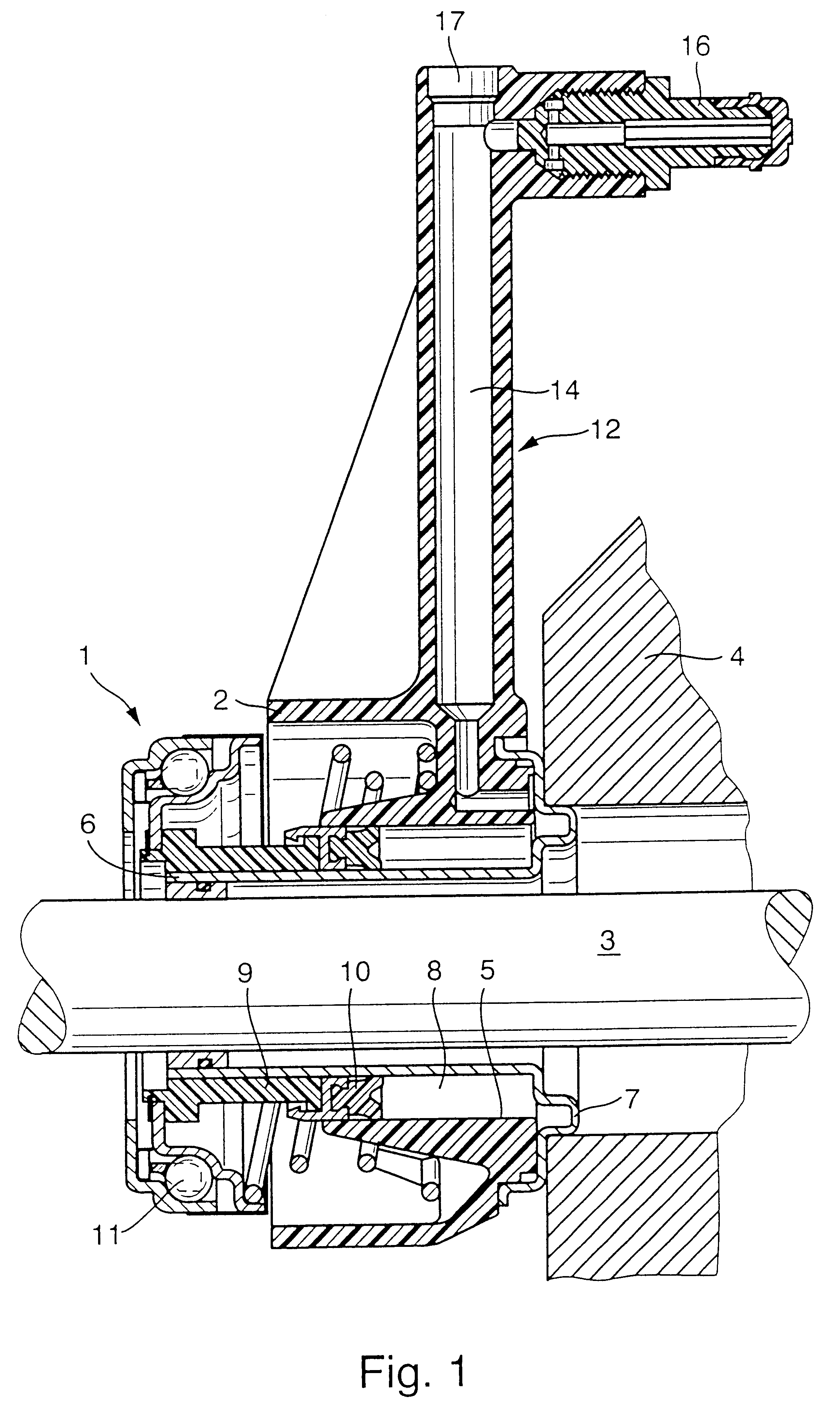
FIG. 1 shows a portion of a hydraulically operated apparatus 1 which is designed to disengage and to cause or permit reengagement of a friction clutch (not shown) in the power train of a motor vehicle. That portion of the improved apparatus 1 which is actually shown in FIG. 1 comprises a so-called central or centrally located slave cylinder and piston unit which is coaxial with an input shaft 3 extending from the stationary housing or case 4 of a change-speed transmission. The case 4 serves as a support or carrier for the tubular synthetic plastic outer wall 2 of a composite cylinder of the slave cylinder and piston unit.

Reference may be had, for example, to FIG. 1B in commonly owned U.S. Pat. No. 5,632,706 granted May 27, 1997 to Burkard Kremmling et al. for "MOTOR VEHICLE WITH ELECTRONIC CLUTCH MANAGEMENT SYSTEM". In contrast to the apparatus 1 of the present invention, the power train shown in FIG. 1B of the '706 patent employs a slave cylinder and piston unit (2) having a piston...


PUM


Abstract

The cylinder of a cylinder and piston unit in the friction clutch engaging/disengaging apparatus of a power train for use in a motor vehicle is assembled of two separately produced coaxial tubular walls. The outer wall is made of a plastic material and is of one piece with an extension serving to supply pressurized hydraulic fluid from a pump or another source to the plenum chamber for the reciprocable annular piston between the two walls. The inner wall is made of sheet metal and one of its end portions is separably coupled to one end portion of the outer wall by snap action. Such one end portion of the outer wall is separably secured to a support, usually the transmission case in the power train of the motor vehicle.

Description

The invention relates to friction clutches and to assemblies which employ engageable and disengageable friction clutches, and more specifically to improvements in apparatus for operating friction clutches, especially in the power trains of motor vehicles. Such clutches are engaged when the prime mover (such as an internal combustion engine and / or an electric machine) drives or is driven by the wheels of the motor vehicle but are disengaged during shifting of the transmission into a gear ratio or into a different gear ratio.German patent No. 43 13 346 discloses a so-called central clutch engaging and disengaging apparatus (hereinafter called apparatus or clutch actuating apparatus). The apparatus is a hydralically operated arrangement including a so-called slave cylinder and piston unit which is coaxial with the rotary input element of a change-speed transmission. The unit comprises a cylinder which is separably secured to the case (housing) of the transmission, and an annular piston...

Claims


Application Information

Patent Timeline
Patent Type & Authority Patents(United States)
IPC IPC(8): F16D25/08
CPCF16D25/083
Inventor WELTER, ROLANDSCHAAF, PETERPROSCH, GERHARDSCHNEIDER, BERTHOLD
Owner SCHAEFFLER TECH AG & CO KG
Why Eureka
Try Eureka