Method for producing a stratified composite material

Inactive Publication Date: 2005-12-22
MIBA GLEITLAGER GMBH
View PDF0 Cites 5 Cited by
  • Summary
  • Abstract
  • Description
  • Claims
  • Application Information

AI Technical Summary

Benefits of technology

[0005] Since as a result of these measures the heated metal carrier has a temperature drop starting from a maximum temperature in the region of the surface layer receiving the particle layer in the direction towards a core layer, it is possible, despite the heating of the solids particles of the layer material to the sintering temperature required for a sintering with liquid phase by a heat transmission from the metal carrier, to ensure an outwardly progressing solidification of the liquid phase starting from the surface of the metal carrier. The melting heat withdrawn from the metal carrier from its layer close to the surface leads to a cooling of the layers of the metal carrier close to the surface in the case of a respective adjustment of the relevant conditions as a result of the temperature drop and thus to a solidification of the liquid phase with growing advancement progressing from the inside to the outside. The relevant aspect is a sufficient temperature drop which should be at least 5 K/mm in order to ensure the desired effect in numerous applications.
[0006] Due to the penetration depth of an electromagnetic alternating field into a strip-like metal carrier which depends relevantly on the frequency, the desired temperature profile for the heating of the metal carrier can be achieved advantageously by an inductive heating, since different field densities can easily be set by a respective arrangement of the windings of the exciting winding in the region of the mutually opposite surfaces of the strip-like metal carrier or by a winding arrangement on one side. In this way it is possible to continuously heat the metal carrier

Problems solved by technology

Although this method for producing a stratified composite material can be used to considerably reduce the length of a required installation in comparison with conventional system

Method used


Image

  • Method for producing a stratified composite material
  • Method for producing a stratified composite material
  • Method for producing a stratified composite material

Examples


Example

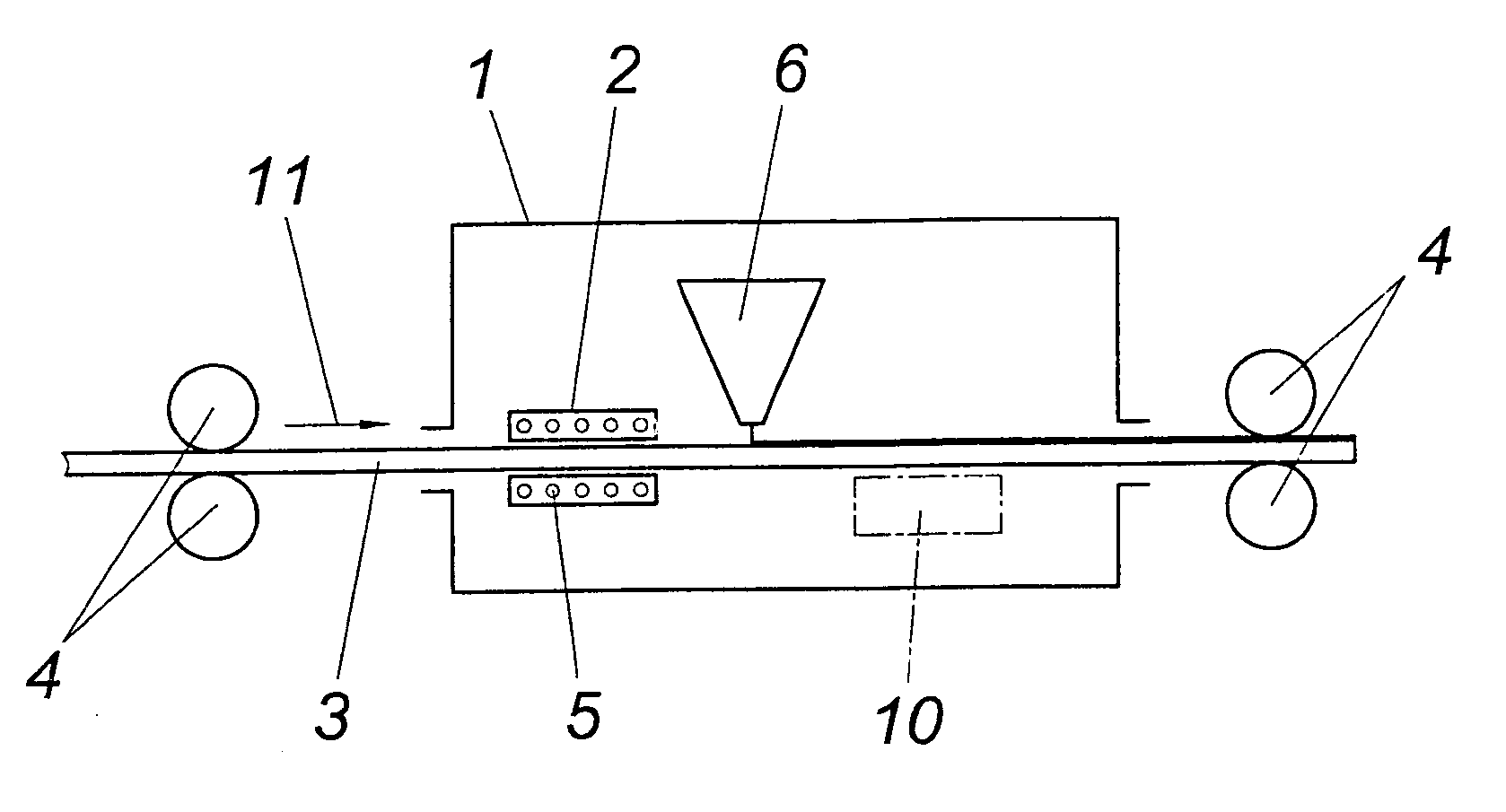
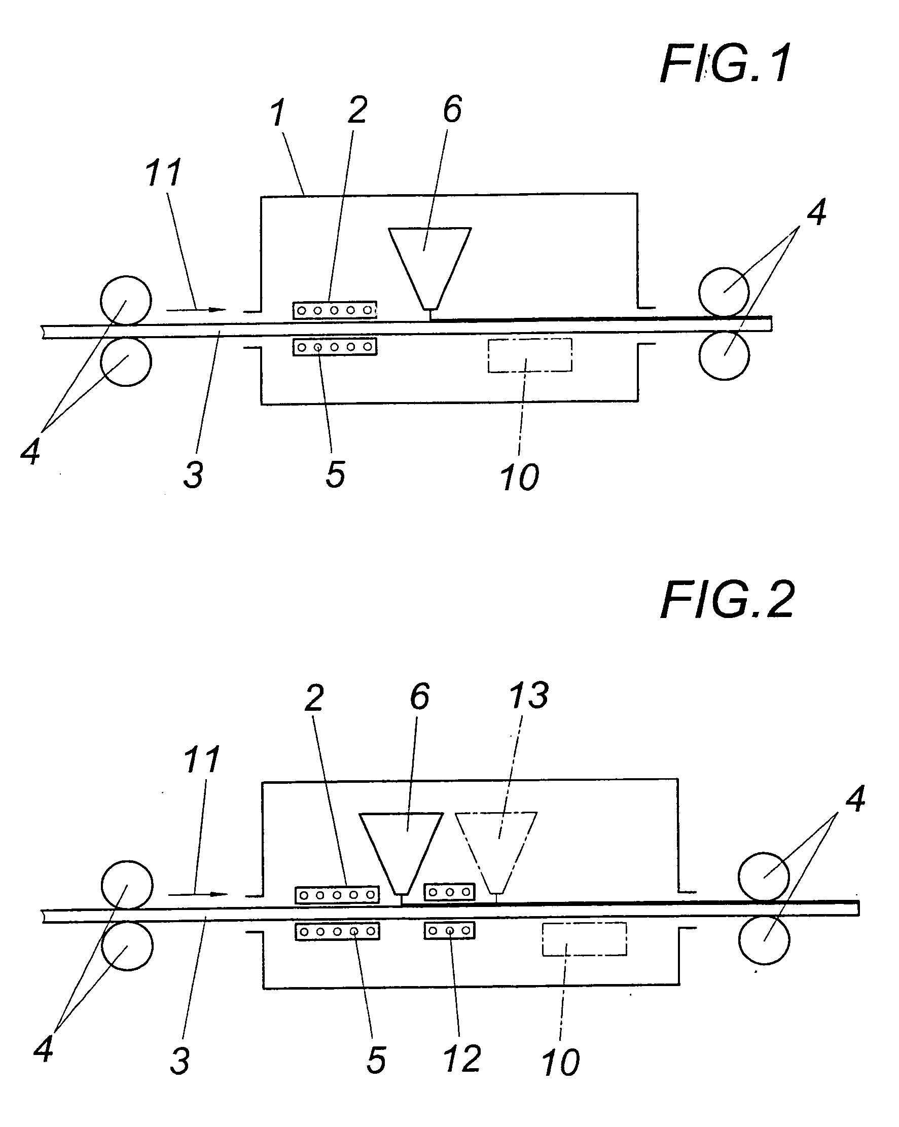
[0013] According to the embodiment according to FIG. 1, a device 2 for the inductive heating of a strip-like metal carrier 3 is provided within a protective hood 1 for maintaining an atmosphere of inert gas, which carrier is conveyed with the help of driving rollers 4 through the protective hood 1 and is heated on passing through the windings 5 of at least one inductive coil before solids particles (e.g. a sintering powder) is applied onto the metal carrier 3 for the applied layer material with the help of a scattering device 6.

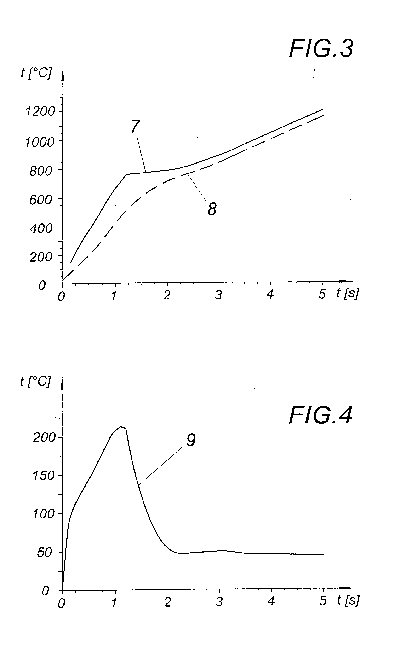
[0014]FIG. 3 shows the heating curve over time for a steel metal carrier 3 with a thickness of 5 mm shown on the one hand in a surface layer and on the other hand in a core layer. The curve 7 of the surface temperature as shown with the unbroken line leads to the consequence that at a suitable field frequency of 200 kHz for example the surface temperature of the metal carrier 3 rises only gradually again after exceeding the Curie point. However, in the case ...


PUM

PropertyMeasurementUnit
Temperatureaaaaaaaaaa
Melting pointaaaaaaaaaa

Abstract

A method is described for producing a stratified composite material, with a layer of sinterable solids particles being applied to a strip-like metal carrier and being sintered with liquid phase by the supply of heat continuously in the forward feed direction. In order to provide simplified production conditions it is proposed that the metal carrier is heated continuously in the forward feed direction with a temperature profile which decreases towards lower temperatures from a maximum temperature above the melting temperature of the solids particles in the region of a surface layer receiving the particle layer towards a core layer of the metal carrier, and that the particle layer is sintered at least in a layer resting on the metal carrier by a heat transmission from the heated metal carrier.

Description

FIELD OF THE INVENTION [0001] The invention relates to a method for producing a stratified composite material, with a layer of sinterable solids particles being applied to a strip-like metal carrier and being sintered with liquid phase by the supply of heat continuously in the forward feed direction. DESCRIPTION OF THE PRIOR ART [0002] In order to enable the production of a stratified composite material which consists for example of a steel carrier and a layer material on the basis of copper and which is used for slide bearings by sintering the layer material which is applied to the steel carrier in powder form without having to guide the strip-like steel carrier with the applied sintering powder through a complex sintering furnace and a downstream cooling apparatus, it is known (GB 2 383 051 A) to melt with the help of laser beams the sintering powder of the layer material sprinkled onto the steel carrier over the width of the strip-like steel carrier in a locally limited longitudi...

Claims


Application Information

Patent Timeline
IPC IPC(8): B05C9/14B05C19/04B05D1/12B05D1/30B05D3/02B05D3/04B05D7/00B05D7/14
CPCB05C9/14B05C19/04B05D1/30B05D3/0245B05D2401/32B05D3/0486B05D7/14B05D7/52B05D2252/02B05D3/0281
Inventor MERGEN, ROBERTKUTZIK, GUNTER
Owner MIBA GLEITLAGER GMBH
Why Eureka
Try Eureka