Method and device for detecting precipitation by radar

a radar and precipitation technology, applied in the direction of measurement devices, instruments, climate sustainability, etc., can solve the problems of different degrees of degradation of radar signals

Inactive Publication Date: 2013-10-15
ROBERT BOSCH GMBH
View PDF25 Cites 5 Cited by
  • Summary
  • Abstract
  • Description
  • Claims
  • Application Information

AI Technical Summary

Benefits of technology

[0011]Evaluating more than two backscattered radar signals increases the accuracy of the detection of precipitation. The backscattered radar signals may be reflections of radar signals that are emitted by adjacent radar transmitters.
[0012]In one preferred specific embodiment, at least one weighting factor may be taken into account in determining the conformity of the average powers, the at least one weighting factor being designed to compensate for different radar antenna characteristics. Using weighting factors makes it possible to compare the average powers even when the radar signals on which they are based derive from radar transmitters having different designs. This increases the flexibility of the method according to the present invention.
[0023]The approach according to the present invention may be used for a multitude of applications. First and foremost, the present invention makes it possible to detect an appearance of precipitation in the radar signal transmission medium. Furthermore, it is possible to determine a precipitation intensity and to estimate a performance loss of the radar transmitter. The present invention may be used to change over or adjust the system, for example, a modulation system, to the current signal transmission medium in order to maintain a restricted functionality of the radar transmitter in bad weather conditions. That is, it is possible to vary the power of the transmitted signals as a function of an ascertained precipitation, for example. A further advantage of the approach according to the present invention is that the method according to the present invention may be used, in part without modification, on existing automotive radar transmitters that generate at least two radiation cones. Future radar transmitters and systems may be optimized such that they are able to utilize the advantages of the present invention. Furthermore, the approach according to the present invention is suitable as a signal source for safety-relevant systems in vehicles.

Problems solved by technology

The degrading effect appears particularly at higher frequencies, as used for example in automotive radar sensors, and depending on the intensity of the precipitation, may produce different degrees of degradation in the radar signal.

Method used


Image

  • Method and device for detecting precipitation by radar
  • Method and device for detecting precipitation by radar
  • Method and device for detecting precipitation by radar

Examples


Embodiment Construction

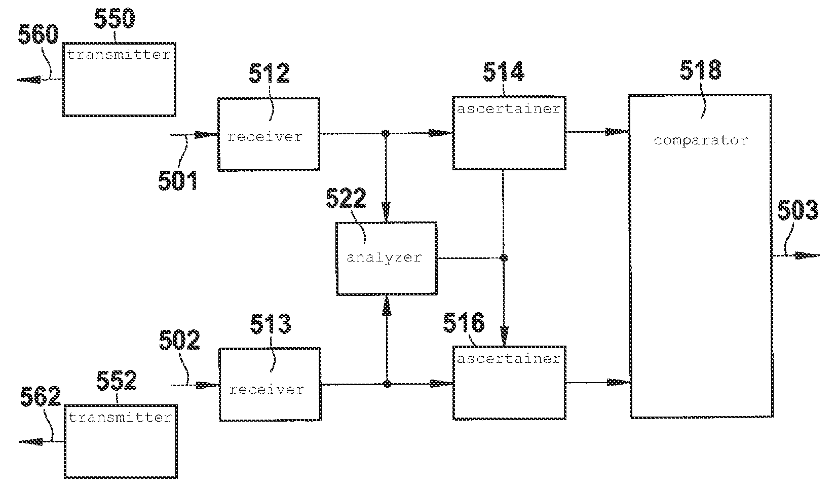
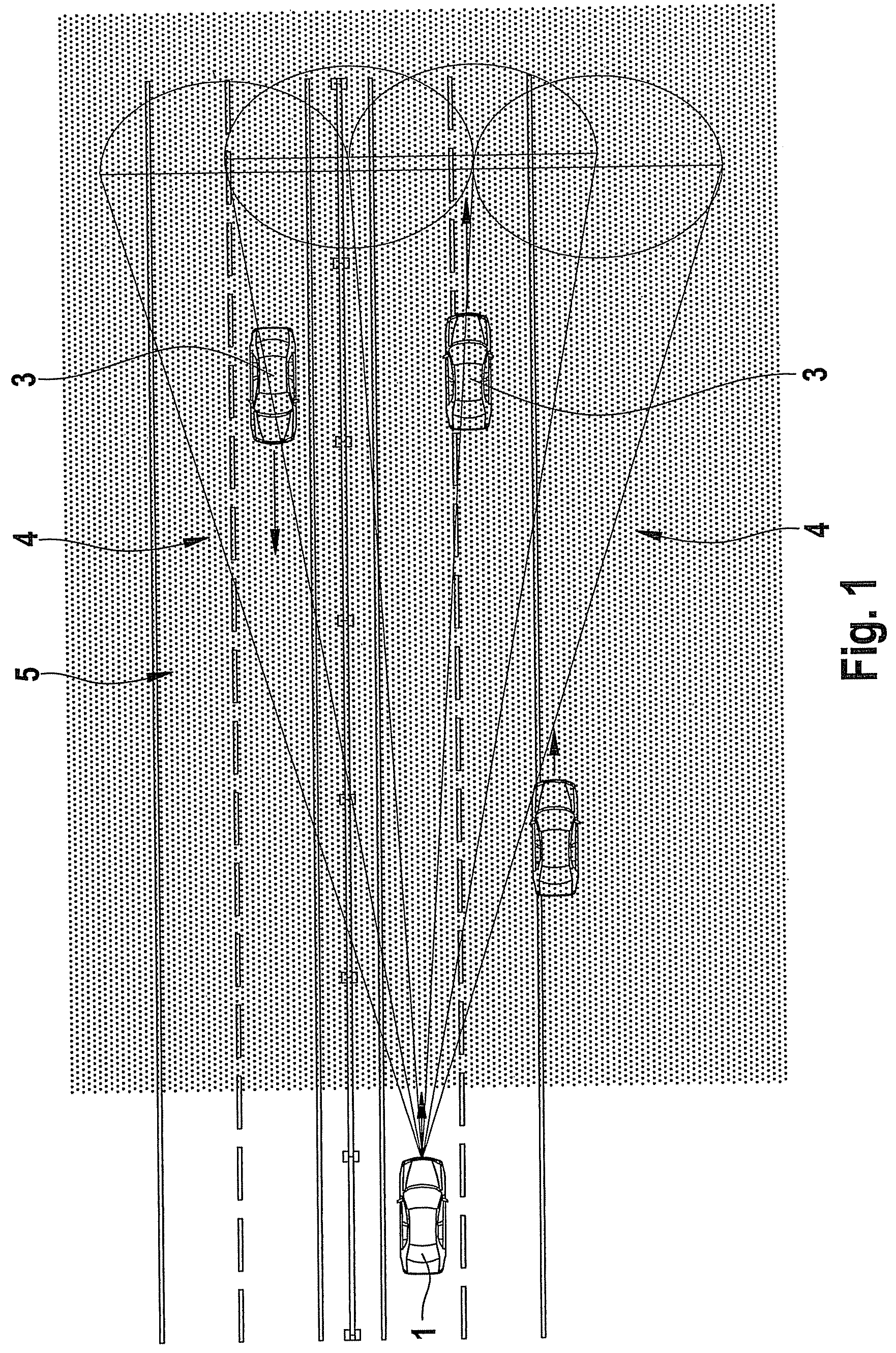
[0031]FIG. 1 shows a use of a multi-beam automotive radar system in road traffic. A vehicle 1, also known as radar vehicle, is equipped with a long-range radar system (LRR). The radar system includes at least one transmitter or antenna, at least one receiver or sensor, and processing means, such as a microprocessor for evaluating backscattered radiation received by the receiver. Transmitter and receiver are expediently designed as an antenna, which carries out transmitting and receiving functions.

[0032]Vehicle 1 moves on a street that may be defined by delimitations, for example, in the form of a guard rail. Additional vehicles 3, which may be monitored by the radar of vehicle 1, move on the street. The radar of vehicle 1 emits a plurality of radar cones or antenna beams 4 to monitor vehicles 3. A region monitored by antenna beams 4 is permeated by precipitation, in this case by rain 5.

[0033]The precipitation's main direction of movement is orthogonal to the radar beams. In the exem...


PUM


Abstract

A method for detecting precipitation in a region monitored by radar beams includes ascertaining a first average power of a first backscattered radar signal, ascertaining a second average power of a second backscattered radar signal, and detecting an existence of a homogenous medium when the average powers conform.

Description

FIELD OF THE INVENTION[0001]The present invention relates to a method, a computer program, and a computer program product for detecting precipitation in a region monitored by radar beams.BACKGROUND INFORMATION[0002]Precipitation, such as rain, hail, fog, or snowfall, may be detected by radar. For example, in meteorology, the intensity of precipitation may be determined via radar, in that a directed antenna emits electromagnetic radiation in the form of a pulse in the microwave range. A radar system that emits radar beams having a wavelength of approximately 3 to 10 cm may be used for this purpose. If the radiation strikes a particle in the atmosphere whose diameter is larger than approximately 0.2 mm, the radiation is reflected by it. The wavelength of the radiation does not change in the process. Part of this radiation is detected by a radar receiver and the reflectivity is measured. If certain assumptions are made about the particle and drop size distribution of the precipitation ...

Claims


Application Information

Patent Timeline
Patent Type & Authority Patents(United States)
IPC IPC(8): G01S13/95G01S13/34G01S13/00
CPCG01S7/411G01S13/956G01S13/87G01S13/931G01S2013/9375G01S2013/93271Y02A90/10
Inventor HASSEN, ALEBEL ARAGE
Owner ROBERT BOSCH GMBH
Why Eureka
Try Eureka