Method for producing a stratified composite material

a composite material and composite material technology, applied in the direction of liquid surface applicators, pretreated surfaces, coatings, etc., can solve the problem of high complexity of the system and achieve the effect of reducing thermal energy

Inactive Publication Date: 2007-01-02
MIBA GLEITLAGER GMBH
View PDF7 Cites 6 Cited by
  • Summary
  • Abstract
  • Description
  • Claims
  • Application Information

AI Technical Summary

Benefits of technology

[0003]It is an object of the invention to provide a method for producing a stratified composite material of the kind mentioned above in such a way that the advantages of sintering in a liquid phase which progresses in the forward feed direction and is limited to a short longitudinal region can be utilized without having to heat the respective layer of the layer material to sintering temperature with the help of laser devices.
[0005]Due to the penetration depth of an electromagnetic alternating field into a strip-like metal carrier which depends on the frequency, the desired temperature profile for the heating of the metal carrier can be achieved advantageously by an inductive heating, since different field densities can easily be set by a suitable arrangement of the windings of an inductive coil in the region of the opposite surfaces of the strip-like metal carrier or by a winding arrangement on one side. In this way it is possible to continuously heat the metal carrier in the forward feed direction with the desired temperature profile in order to transmit the melting heat from the metal carrier onto the applied particle layer which is required for the sintering of the solids particles in a liquid phase. The particle layer can be produced with conventional sintering powders. It is also possible to use coarse-grained materials or granulates without endangering the desired sintering by heat transmission from the metal carrier.

Problems solved by technology

Although this method for producing a stratified composite material can be used to considerably reduce the length of a required installation in comparison with conventional systems for sintering stratified composite materials, the high complexity of the system remains, due to the required use of laser devices over the width of the strip-like steel carrier.

Method used


Image

  • Method for producing a stratified composite material
  • Method for producing a stratified composite material
  • Method for producing a stratified composite material

Examples


Embodiment Construction

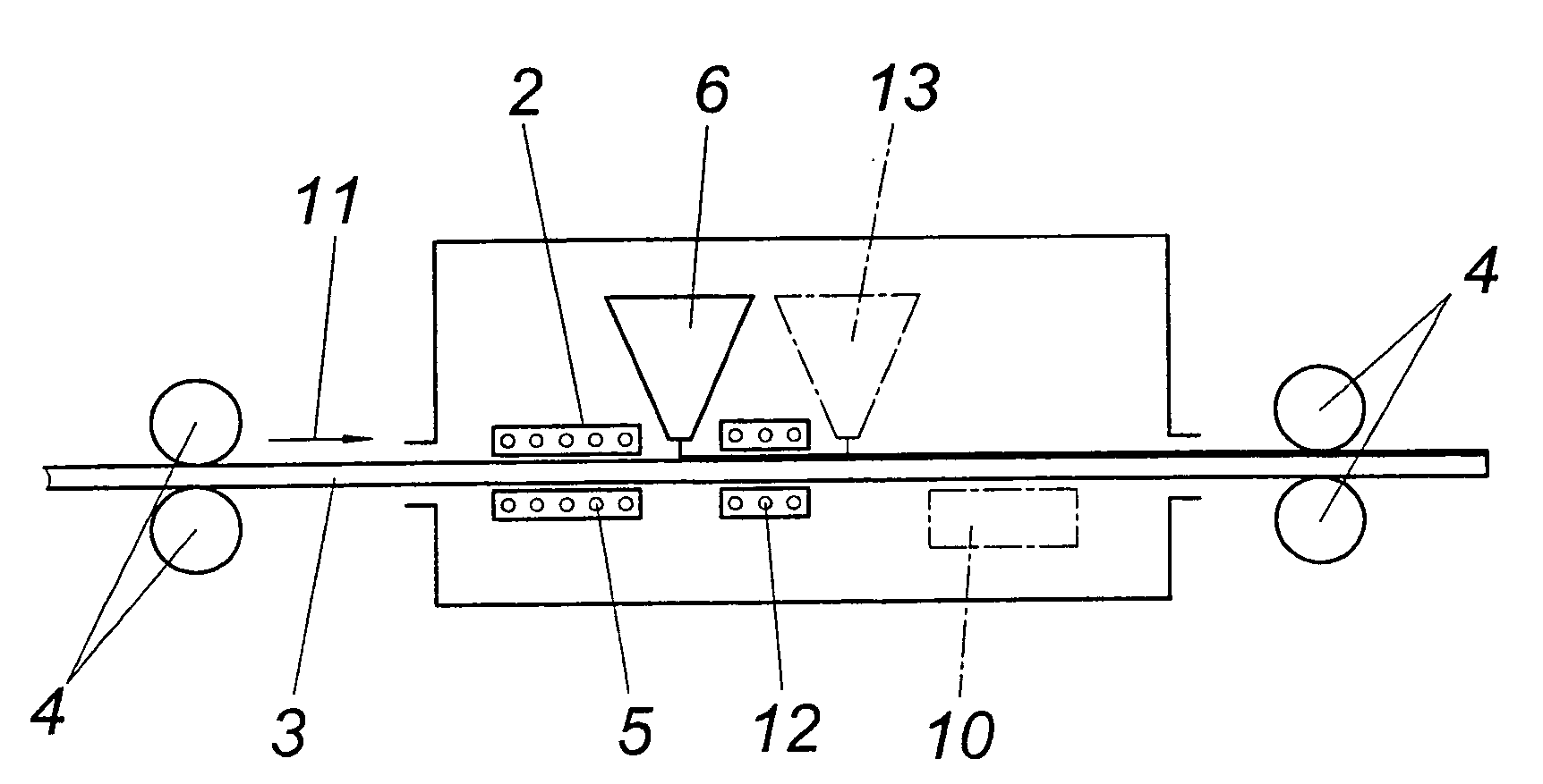
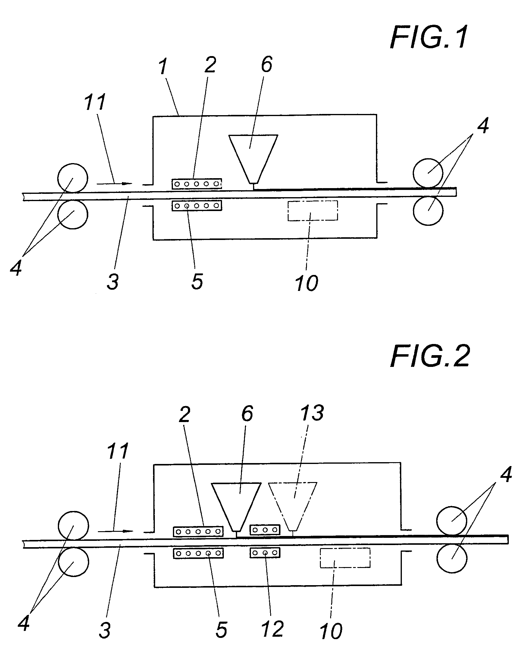
[0012]According to the embodiment according to FIG. 1, a device 2 for the inductive heating of a strip-like metal carrier 3 is provided within a protective hood 1 for maintaining an atmosphere of inert gas, which carrier is conveyed with the help of driving rollers 4 through the protective hood 1 and is heated on passing through the windings 5 of at least one inductive coil before solids particles (e.g. a sintering powder) is applied onto the metal carrier 3 from sprinkling device 6.

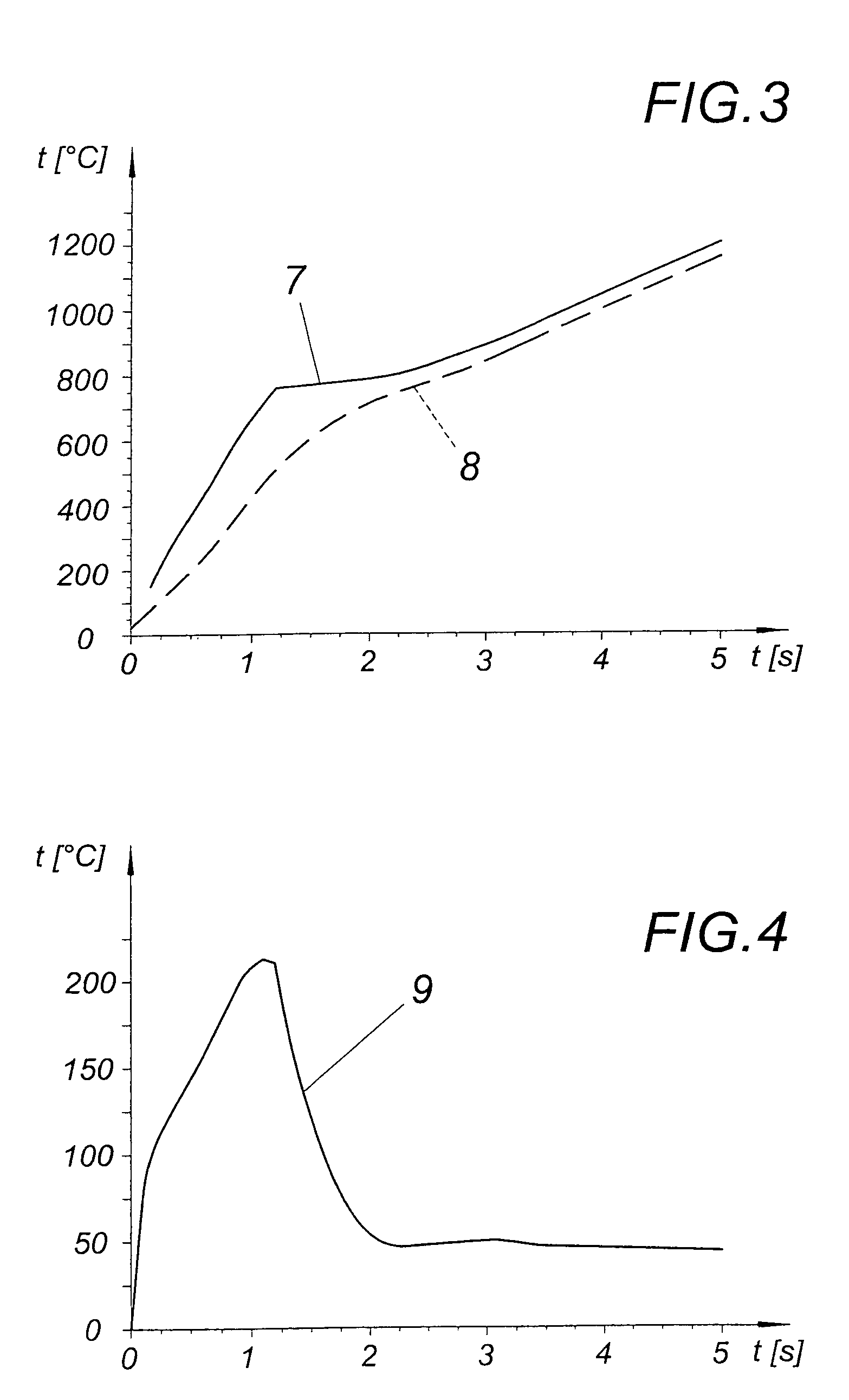
[0013]FIG. 3 shows the curve over time for a steel metal carrier 3 with a thickness of 5 mm in a surface layer and in a core layer. The curve 7 of the surface temperature shows that, at a suitable field frequency of 200 kHz for example, the surface temperature of the metal carrier 3 rises only gradually after exceeding the Curie point. However, with a suitable energy supply, the necessary maximum temperature of 1100° C. to 1200° C. which lies above the melting temperature of the solids particles can easi...


PUM

PropertyMeasurementUnit
thicknessaaaaaaaaaa
temperatureaaaaaaaaaa

Abstract

A method is described for producing a stratified composite material, with a layer of sinterable solids particles being applied to a strip-like metal carrier and being sintered with liquid phase by the supply of heat continuously in the forward feed direction. In order to provide simplified production conditions it is proposed that the metal carrier is heated continuously in the forward feed direction with a temperature profile which decreases towards lower temperatures from a maximum temperature above the melting temperature of the solids particles in the region of a surface layer receiving the particle layer towards a core layer of the metal carrier, and that the particle layer is sintered at least in a layer resting on the metal carrier by a heat transmission from the heated metal carrier.

Description

FIELD OF THE INVENTION[0001]The invention relates to a method for producing a stratified composite material, wherein a layer of sinterable solids particles is applied to a strip-like metal carrier and is sintered in a liquid phase by the supply of heat continuously in a forward feed direction.DESCRIPTION OF THE PRIOR ART[0002]It is known (GB 2,383,051A) to produce a stratified composite material, which consists, for example, of a steel carrier and a copper based layer material and which is used for slide bearings, by sintering the layer material which is applied to the steel carrier in powder form and to melt with the help of laser beams the powder of the layer material sprinkled onto the steel carrier over the width of the strip-like steel carrier in a locally limited longitudinal region. The same is then rapidly cooled from the side of the steel carrier in order to achieve an outwardly progressing solidification of the layer material, starting from the surface of the steel carrier...

Claims


Application Information

Patent Timeline
Patent Type & Authority Patents(United States)
IPC IPC(8): B22D11/00B05D1/12B22D19/08B22F7/04B05C9/14B05C19/04B05D1/30B05D3/02B05D3/04B05D7/00B05D7/14
CPCB05D3/0245B05D7/14B05C9/14B05C19/04B05D1/30B05D2401/32B05D3/0486B05D7/52B05D2252/02B05D3/0281
Inventor MERGEN, ROBERTKUTZIK, GUNTER
Owner MIBA GLEITLAGER GMBH
Why Eureka
Try Eureka