Hybrid power relay

Inactive Publication Date: 2002-02-12
CROUZET AUTOMATISMES SA
View PDF3 Cites 41 Cited by
  • Summary
  • Abstract
  • Description
  • Claims
  • Application Information

AI Technical Summary

Problems solved by technology

One consequence of the carbonizing is the degradation in the quality of the contact owing to the increase in the resistance to the flow of current.
However, static relays have a drawback compared with electromechanical relays.
Actuation of the hybrid relay simultaneously causes the semiconductor component to be turned on, which component absorbs the switching arc, and causes the contact of the relay to close, which short-circuits the semiconductor component.
However, this solution has drawbacks, namely that an increase in the resistance be

Method used


Image

  • Hybrid power relay
  • Hybrid power relay
  • Hybrid power relay

Examples


Example

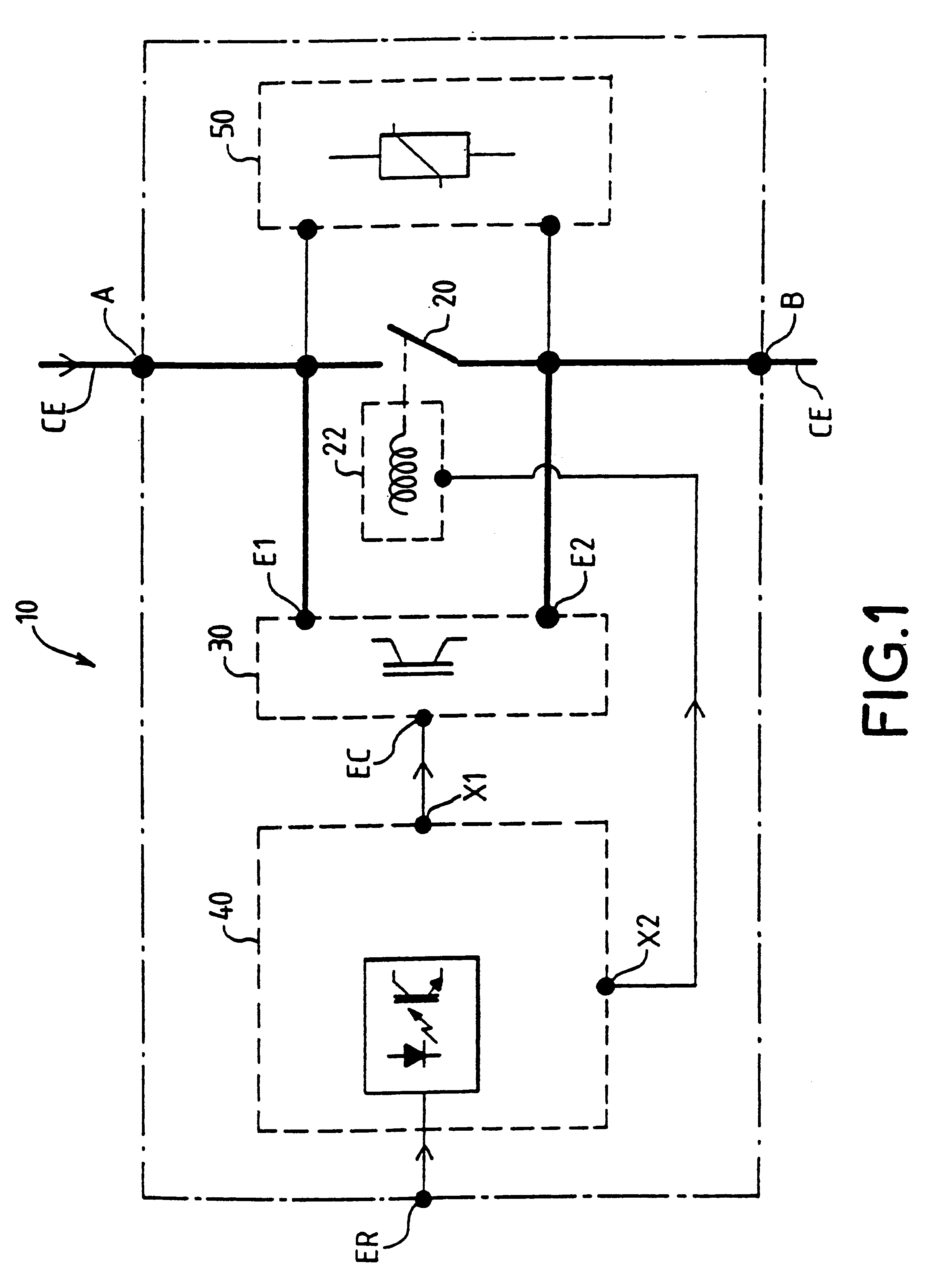
A hybrid power relay 10 has two terminals A and B intended to be inserted into an electrical circuit CE. The hybrid relay is opened or closed by a control input ER of the hybrid relay 10.

The hybrid relay 10 essentially comprises:

an electrical contact 20 having a mechanical movement, connected between the two terminals A and B of the hybrid relay;

a coil 22 which actuates the contact 20 so as to close it or open it;

a semiconductor component 30 having two power inputs E1 and E2, which is connected in parallel with the contact 20 via these two power inputs, and a control input EC for turning it on.

Control means include a control circuit 40 having the control input ER of the hybrid relay, a first output X1 which is fed to the control input EC of the semiconductor component 30, and a second output X2 supplying the coil 22.

The hybrid power relay 10 may furthermore include a protection device 50 connected between the terminals A and B so as to protect the hybrid relay from possible overvolt...


PUM


Abstract

Hybrid power relay used for opening or closing electrical circuits, including an electrical contact having a mechanical movement, a semiconductor component in parallel with the electrical contact, and a control unit which in response to a logic input level causes the electrical contact to close (open) and the semiconductor component to be turned on. The control unit generates a contact-make signal for closing the contact, and a control signal that turn on the semiconductor component for a predetermined period of time. The control signal prevents the semiconductor component from being turned on after the predetermined period if the electrical contact fails to close so that the semiconductor component is undamaged. Also, the control unit generates a contact-break signal for opening the electrical contact, and turning on the semiconductor component before the electrical contact has opened by means of a control signal which terminates at the end of a second predetermined period after the electrical contact has opened.

Description

1. Field of the InventionThe invention relates to hybrid power relays used for opening or closing electrical circuits.2. Discussion of the BackgroundAt the present time there are two main types of relays according to their operating technologies--electromechanical relays and semiconductor or static relays.The relays are designed to withstand the current of the electrical circuit into they are inserted and to cut off the electrical circuit under load, that is to say when an electric current flows through the circuit.Electromechanical-type relays comprise one or more electrical contacts having a mechanical movement, these being coupled to a moveable element of the magnetic circuit of an electromagnet. The electromagnet is actuated by supplying power to its coil, which produces an induction flux in the magnetic circuit which causes the moveable element to move and the electrical contacts of the relay to open or close.The switching of an electrical circuit under load by an electromechan...

Claims


Application Information

Patent Timeline
IPC IPC(8): H01H9/54H01H9/56
CPCH01H9/542H01H2009/545H01H2009/544H01H9/56
Inventor BLAIN, GERARDRAFFESTIN, LUC
Owner CROUZET AUTOMATISMES SA
Why Eureka
Try Eureka