
Control system for a linear vibration motor

a control system and vibration motor technology, applied in the direction of motor/generator/converter stopper, dynamo-electric converter control, mechanical energy handling, etc., can solve the problems of difficult to reduce the vibration motor into a compact structure with a reduced cost, and add additional costs

Inactive Publication Date: 2002-02-26
MATSUSHITA ELECTRIC WORKS LTD
View PDF8 Cites 34 Cited by
  • Summary
  • Abstract
  • Description
  • Claims
  • Application Information

AI Technical Summary

Benefits of technology

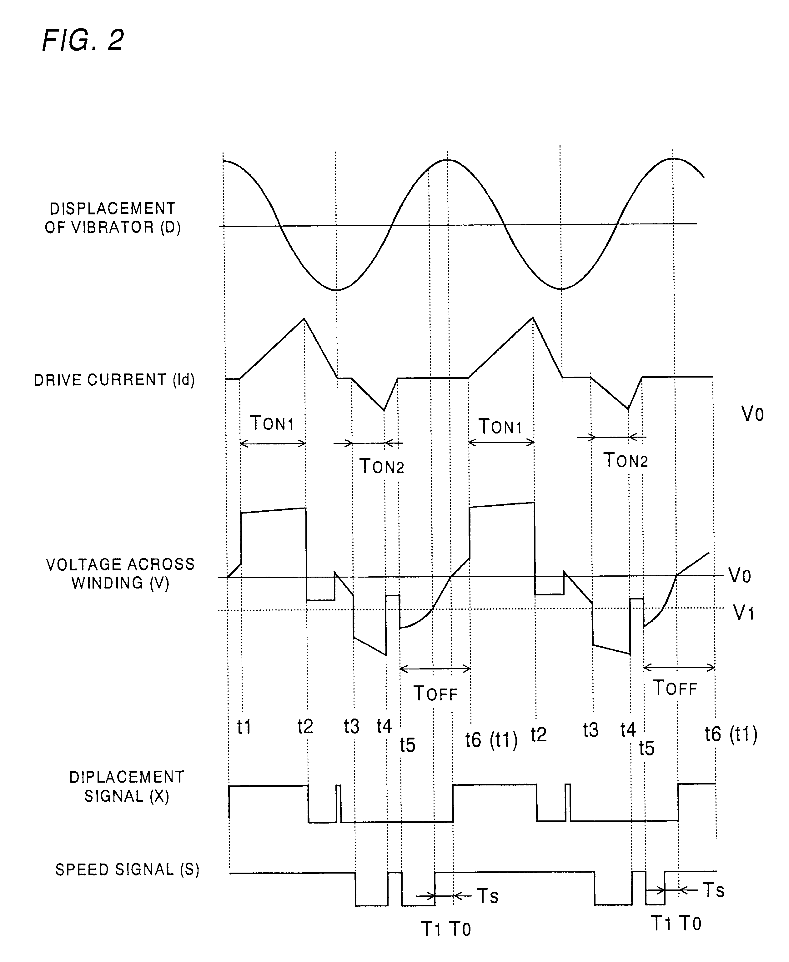
The vibrator vibrates at substantially a fixed frequency. Due to the know frequency, the controller provides a first OFF-period which is set to continue for a predetermined duration within which the vibrator is expected to reach a maximum displacement. Then, the controller determines a reference time within the first OFF-period when the voltage across the winding becomes zero as indicative of that the vibrator reaches the maximum displacement. Based upon the reference time, the controller determines a subsequent ON-period after a first predetermined time interval from the reference time, and determines a subsequent OFF-period after a second time interval from the reference time. Thus, the reference time can be renewed each time the voltage becomes zero in the OFF-period, enabling to provide the subsequent ON-period as well as OFF-period accurately for consistent control of the linear motor.
Preferably, the controller is designed to feed the drive current partly in the form of a pulse-width-modulated (PWM) signal during a first fraction ON-period of variable width and the rest in the form of a fixed width signal during a second fraction ON-period of fixed width. The first ON-period occurs in a half cycle of a particular cycle of the vibration, while the second ON-period occurs in the other half cycle of the same cycle so that the OFF-period occurs together with the second ON-period within the other half cycle. Thus, the vibrator can receive driving forces which are generated respectively in the half cycles and act in opposite moving directions, thereby making efficiently controlled vibration.
The controller is preferred to include a low amplitude compensator which monitors the ongoing amplitude of the vibration and issues a restriction signal when the ongoing amplitude is lower than a minimum reference amplitude. In response to the restriction signal, the controller disables to provide the OFF-period and at the same time elongates the ON-period to feed the drive current to a maximum extent over the following predetermined cycles of said vibration. Thus, the vibrator can be rapidly restored to vibrate at the intended amplitude.

Problems solved by technology

However, this control system requires the coil sensor which gives an additional cost and requires an additional space for the sensor, making it difficult to reduce the vibration motor into a compact structure with a reduced cost.
Thus, the actuator necessitates at least two windings, which is a still hindrance to compacting the structure.
In this prior art, the equivalent circuit adds an extra bulk to the structure, making it difficult to achieve a compact design for the linear motor.

Method used


Image

  • Control system for a linear vibration motor
  • Control system for a linear vibration motor
  • Control system for a linear vibration motor

Examples


Embodiment Construction

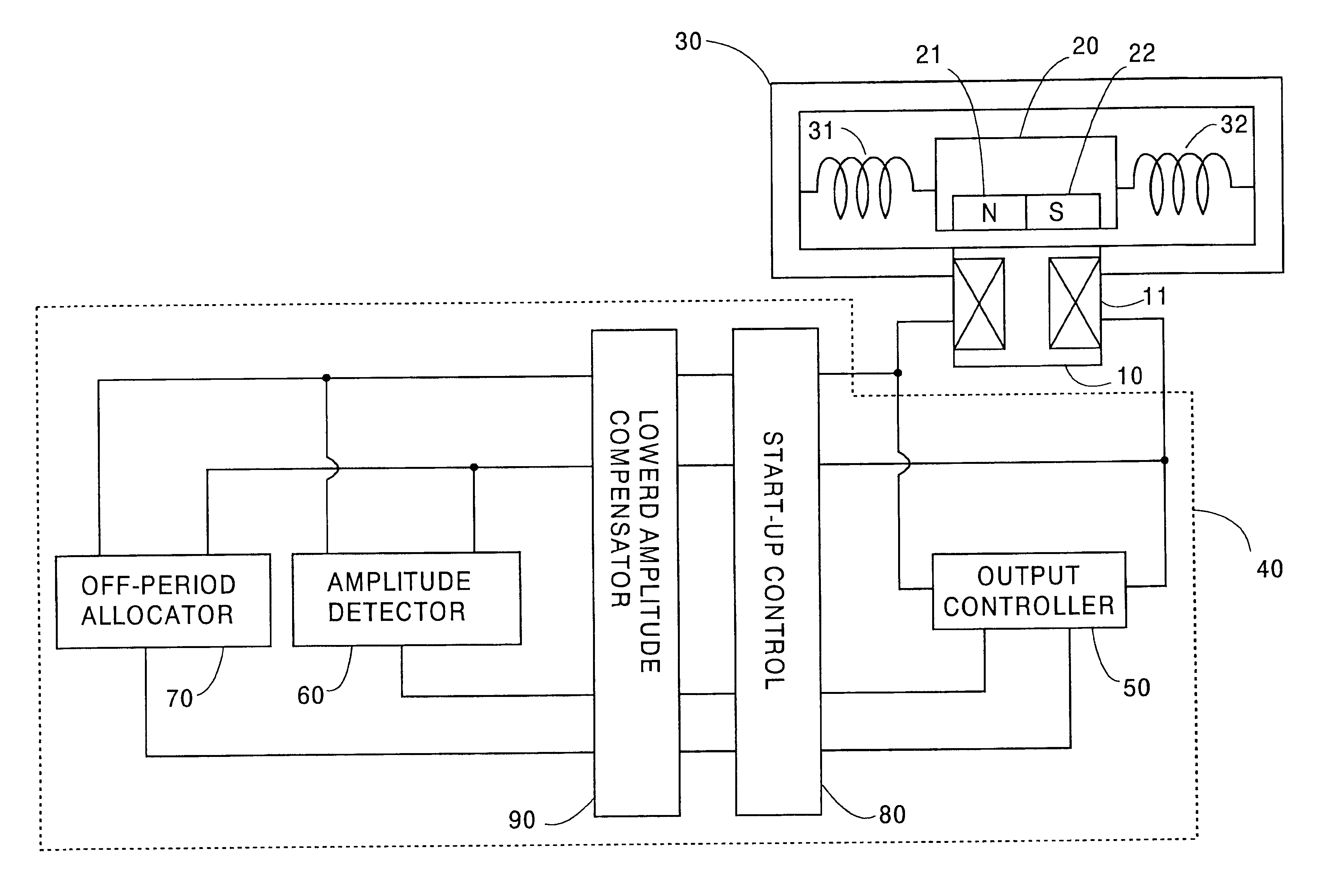
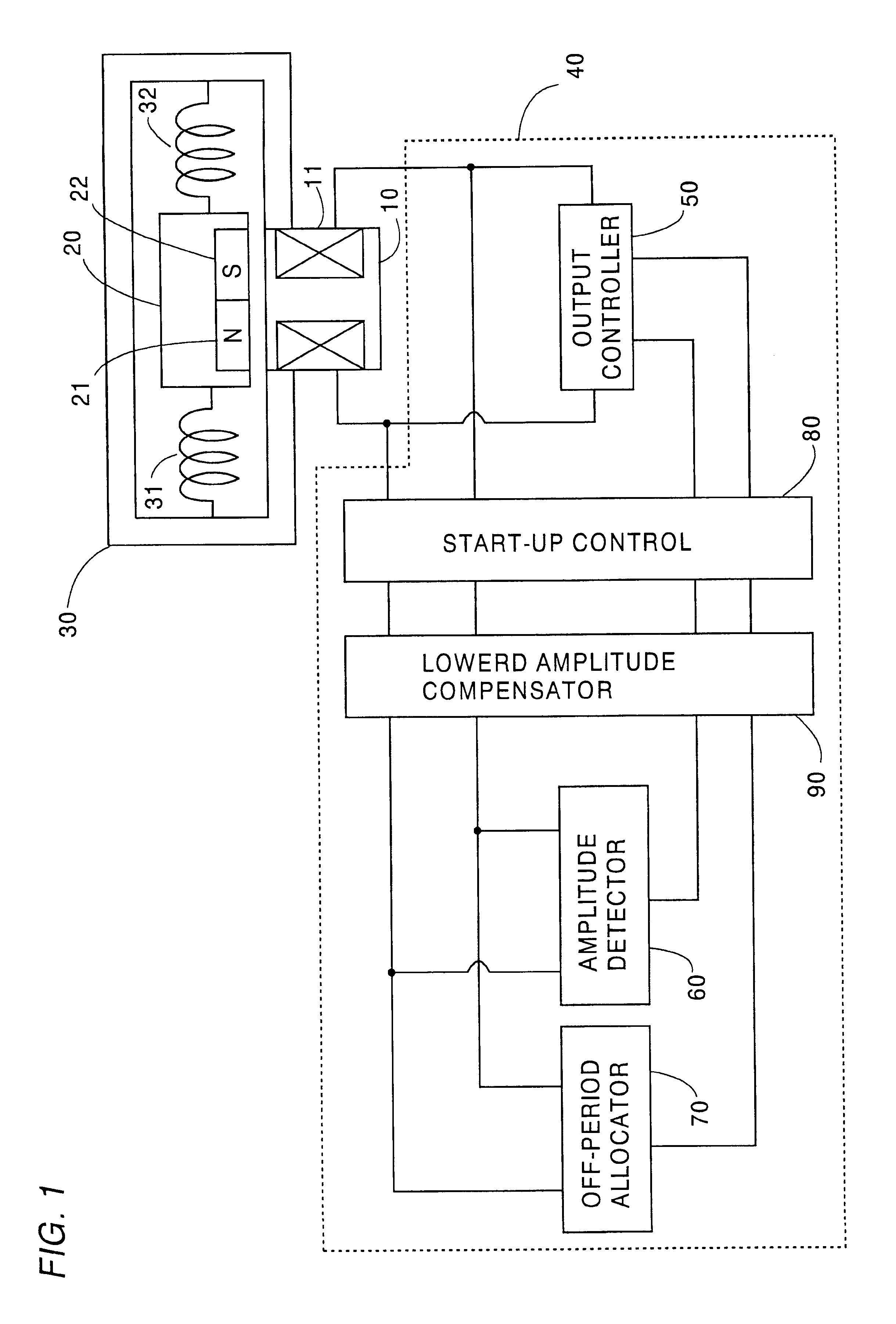
Referring now to FIG. 1, there is shown a control system for a linear vibration motor in accordance with a preferred embodiment of the present invention. The liner vibration motor comprises a stator 10 with a single winding 11 and a vibrator 20 embedded with a set of permanent magnets 21 and 22. The stator 10 is mounted to a frame 30 to which the vibrator 20 is coupled by means of springs 31 and 32. The winding 11 is energized by a controller 40 to generate a magnetic field which interacts with the permanent magnets 21 and 22 to develop a driving force of vibrating the vibrator 20 linearly with respect to the stator 10 between the opposite ends of the frame 30. The springs 31 and 32 are cooperative with a magnetic compliance of the motor to give an oscillation system having a natural frequency so that the vibrator 20 vibrates at substantially a fixed frequency.

The controller 40 includes an output controller 50 which is connected to supply a driving current in the form of a pulse-wid...


PUM


Abstract

A control system for a linear vibration motor capable of eliminating necessity of a separate sensor of detecting the motion of the motor. The linear vibration motor includes a stator provided with a winding, and a vibrator provided with a permanent magnet. The winding is fed with a drive current to generate a magnetic field which interacts with the permanent magnet to cause the vibrator to reciprocate linearly relative to the stator for producing a vibration. The control system includes a controller which detects an ongoing amplitude, i.e., the motion represented by the displacement, speed, or acceleration of the vibrator and provides ON-periods of feeding the driving current to the winding in a varying amount based upon the ongoing amplitude detected in order to keep a vibration amplitude of the vibrator constant. The controller is characterized to provide OFF-period in which the controller instructs not to feed the drive current and in which the controller detects a voltage developed across the winding and determines the ongoing amplitude based upon the detected voltage. Thus, the winding can be best utilized commonly to drive the motor and to sense the ongoing amplitude or motion of the vibrator, thereby eliminating an additional sensor for detection of the motion of the vibrator.

Description

1. Field of the InventionThe present invention is directed to a control system for a linear vibration motor, and more particularly to a system of driving a vibrator linearly with respect to a stator at a uniform amplitude.2. Description of the Prior ArtU.S. Pat. No. 5,632,087 discloses a linear vibration motor composed of a stator with a winding and a vibrator with a permanent magnet. A drive current is fed to the winding to generate a magnetic field with interacts with the permanent magnet to reciprocate the vibrator linearly relative to the stator. A coil sensor is additionally provided in an opposed relation with permanent magnets embedded in the vibrator to produce a voltage which is indicative of the speed of the vibrator, i.e., an ongoing amplitude of the vibrator in motion. Based upon the ongoing amplitude, a control is made to vary the drive current in order to keep the amplitude constant at a desired level. However, this control system requires the coil sensor which gives a...

Claims


Application Information

Patent Timeline
Patent Type & Authority Patents(United States)
IPC IPC(8): H02P25/02H02P25/06H02K33/06H02K33/10
CPCH02P25/027H02P25/032
Inventor IBUKI, YASUOAMAYA, HIDETOSHIOKAMOTO, TOYOKATSU
Owner MATSUSHITA ELECTRIC WORKS LTD
Learn More