Audio decoding apparatus, signal processing device, sound image localization device, sound image control method, audio signal processing device, and audio signal high-rate reproduction method used for audio visual equipment

a signal processing and audio signal technology, applied in the field of audio decoding apparatus, can solve the problems of excessive hardware load, adverse effect of occupation on other processing performed by external memory devices, and inability to reproduce multi-channel audio signals at home,

Inactive Publication Date: 2002-03-12
PANASONIC CORP
View PDF9 Cites 40 Cited by
  • Summary
  • Abstract
  • Description
  • Claims
  • Application Information

AI Technical Summary

Problems solved by technology

Such an occupation has an adverse effect on other processing performed by the external memory device 500.
However, reproduction of a multi-channel audio signal at home is limited, since most of the general home-use TVs have two or less output channels.
When the number of filters and/or the number of channels increase, the load imposed on the operation rate and the hardware becomes excessively large for practical use.
When the number of taps is excessively small, the sound image is blurred or the sound qualit

Method used


Image

  • Audio decoding apparatus, signal processing device, sound image localization device, sound image control method, audio signal processing device, and audio signal high-rate reproduction method used for audio visual equipment
  • Audio decoding apparatus, signal processing device, sound image localization device, sound image control method, audio signal processing device, and audio signal high-rate reproduction method used for audio visual equipment
  • Audio decoding apparatus, signal processing device, sound image localization device, sound image control method, audio signal processing device, and audio signal high-rate reproduction method used for audio visual equipment

Examples


example 2

(Example 2)

A signal processing device 1200 in a second example according to the present invention will be described with reference to FIGS. 9, 10, 11 and 18.

With reference to FIG. 9, a structure and operation of the signal processing device 1200 will be described.

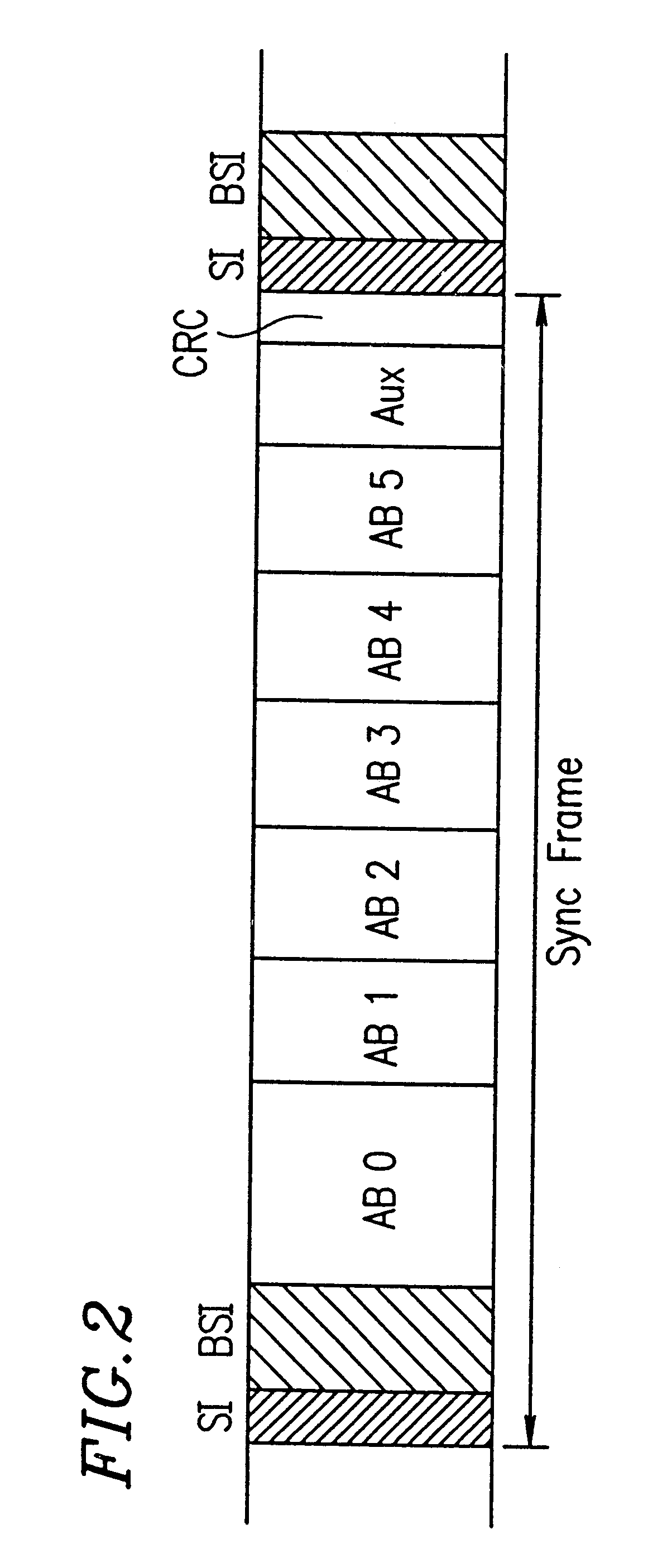
A bit stream which is input to the signal processing device 1200 is formed by first converting each of audio signals corresponding to multiple channels into frequency domain data and encoding the frequency domain data so as to be represented by mantissa sections and exponential sections. Such a bit stream includes audio data for a plurality of channels.

The channels include a normal channel, which includes a high frequency band and a low frequency band. The channels include a basic channel, which includes a high frequency band shared by a plurality of other channels and a low frequency band (channel 1400 shown in FIG. 21). The channels include a coupling channel, which includes a low frequency band previously separated from ...

example 3

(Example 3)

A signal processing device in a third example according to the present invention will be described with reference to FIGS. 9 and 12. The signal processing device in the third example has the same structure as in the second example shown in FIG. 9. The processing shown in FIG. 12 is performed in lieu of the processing shown in FIG. 10, and then the processing shown in FIG. 11 is performed. The elements of the signal processing device in the third example bear the same reference numerals as those in the second example.

The processing shown in FIG. 12 is different from the processing in FIG. 10 in that step S41 is executed between steps S22 and S23.

In step S20, it is determined whether or not the target channel is a coupling channel previously separated from the high frequency band. When the target channel is a coupling channel ("yes"), the mantissa sections of the encoded data for the low frequency band for the channel are decoded to form mantissa data and the mantissa data ...

example 4

(Example 4)

A signal processing device in a fourth example according to the present invention will be described with reference to FIGS. 13 and 14. The signal processing device in the fourth example has the same structure as in the second example shown in FIG. 9, and performs processing as shown in FIGS. 10, 13 and 14. The elements of the signal processing device in the fourth example bear the same reference numerals as those in the second example.

The mantissa sections for each of the channels are processed as shown in FIG. 10 and the description thereof will be omitted.

In the second example, before the processing shown in FIGS. 10 and 11, the exponential sections for each of the target channels are read and decoded, and the resultant exponential data is stored in the operation area of the internal memory device 702, in the fourth example, such decoding of the exponential sections is not performed before the processing shown in FIGS. 13 and 14, The exponential sections are decoded by ...


PUM


Abstract

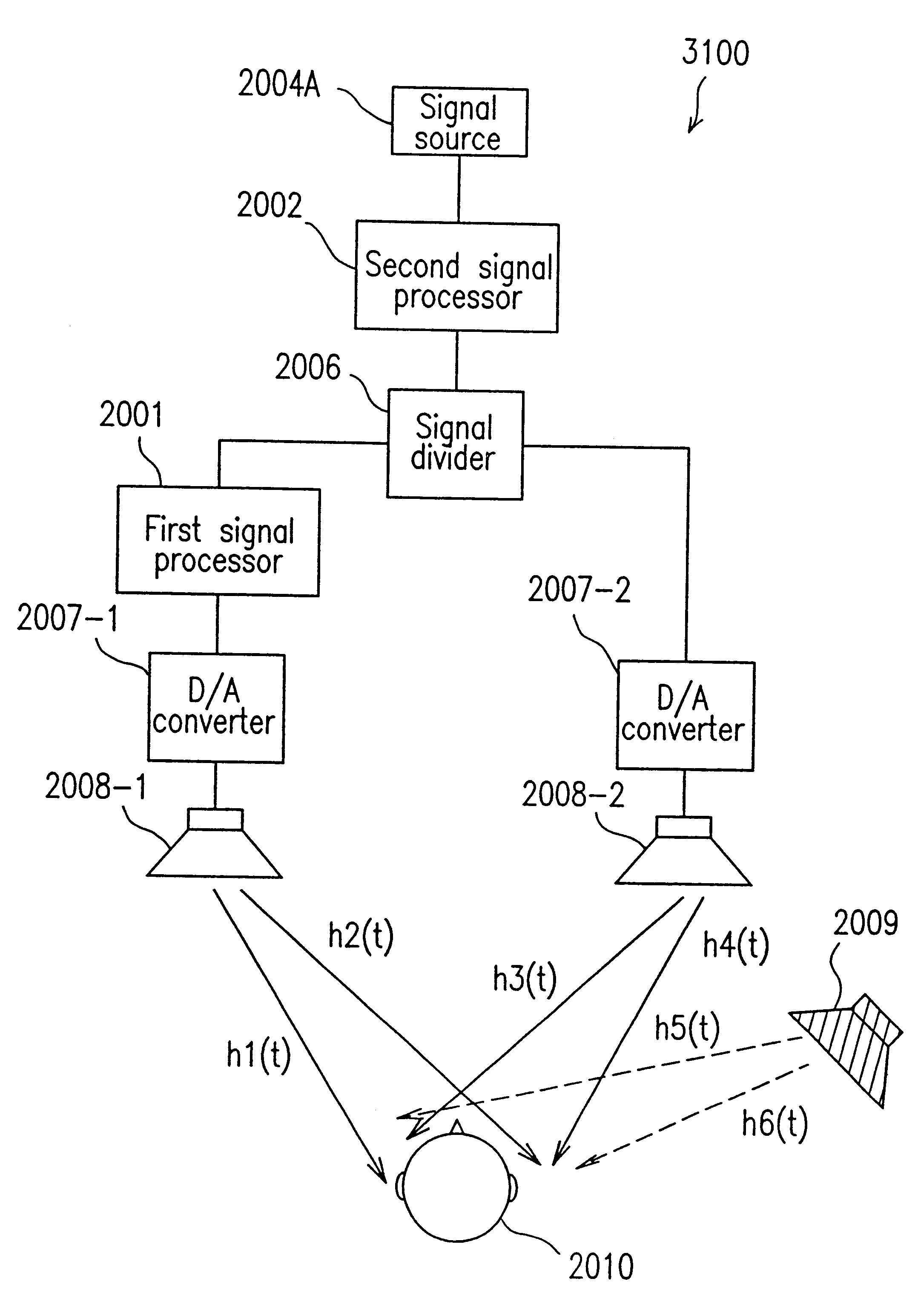
A sound image localization device which includes a signal source for outputting an audio signal, a signal divider for dividing the audio signal output from the signal source into two digital audio signals respectively for two channels, and a first signal processor for receiving one of the two digital signals and processing the digital signal so as to localize a virtual sound image using a filter having a first frequency characteristic. In addition, the sound image localization device includes a first D/A converter for converting the digital signal output from the first signal processor into an analog signal, a second D/A converter for receiving the other digital signal obtained from the signal divider and converting the signal into an analog signal, a first control speaker for outputting the audio signal obtained by the first D/A converter to a prescribed space area; and a second control speaker for outputting the audio signal obtained by the second D/A converter to a prescribed space area.

Description

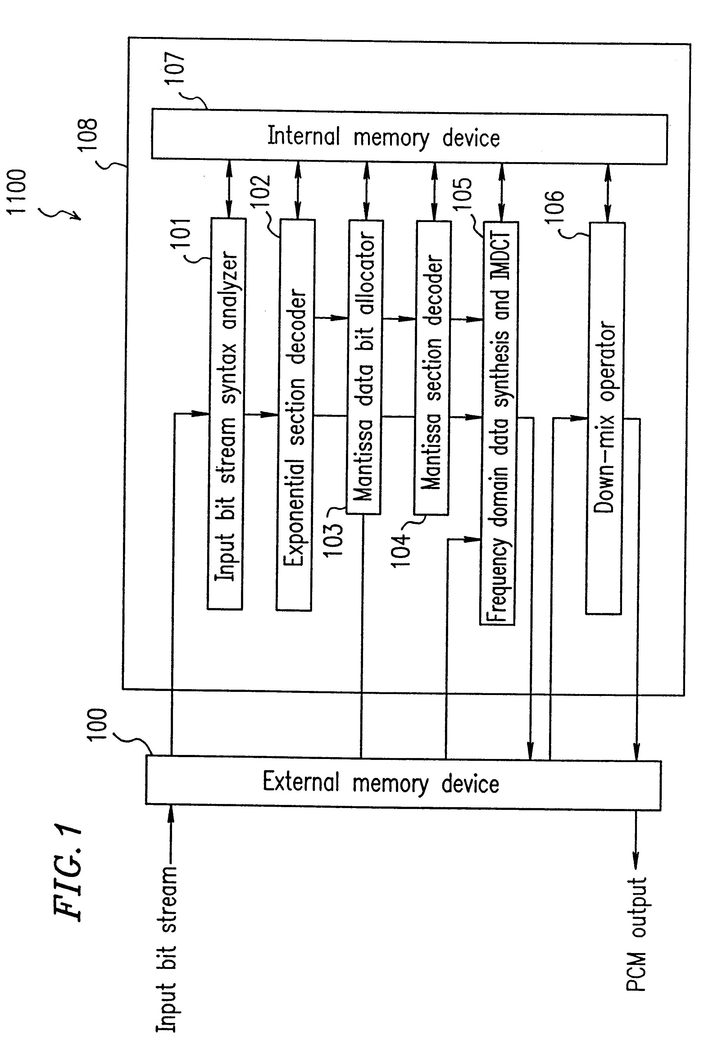
1. Field of the InventionThe present invention relates to an audio decoding apparatus used in AV (audio visual) equipment for decoding an encoded bit stream into PCM data. The present invention also relates to a signal processing device, a sound image localization device, a sound image control method, an audio signal processing device, and an audio signal high-rate reproduction method also used in AV equipment.2. Description of the Related ArtA conventional audio decoding apparatus 550 will be described with reference to FIGS. 6, 7 and 8. FIG. 6 is a block diagram illustrating a structure of the conventional audio decoding apparatus 550. The audio decoding apparatus 550 includes an integrated semiconductor device 508. The integrated semiconductor device 508 includes an input bit stream syntax analyzer 501, an exponential section decoder 502, a mantissa data bit allocator 503, a mantissa section decoder 504, an IMDCT 505, a down-mix operator 506, and an internal memory device 507. Th...

Claims


Application Information

Patent Timeline
IPC IPC(8): G10L21/04G10L21/00H04B1/66H04N7/52H04N5/60G11B20/00
CPCG10L21/04H04B1/665H04N21/4341H04N21/2368H04N5/602H04N21/4398H03M7/40
Inventor ISHITO, TSUKURUMATSUMOTO, MASAHARUMIYASAKA, SHUJIFUJITA, TAKESHIKATAYAMA, TAKASHISUEYOSHI, MASAHIROABE, KAZUTAKANAKAMURA, TSUYOSHIOTOMURA, EIJIKAWAMURA, AKIHISA
Owner PANASONIC CORP
Why Eureka
Try Eureka