Front-loading adjustable safety utility knife with safety quick-release lock

Inactive Publication Date: 2002-03-19
OLYMPIA IND +1
View PDF11 Cites 74 Cited by
  • Summary
  • Abstract
  • Description
  • Claims
  • Application Information

AI Technical Summary

Problems solved by technology

However, with this design, when the handle parts are separated for any reason, the mechanical parts or components which position and move the blade can themselves be separated from and be dislodged from the handle, making it possible for these parts to be misplaced.
This may be difficult and inconvenient due to the presence of a loose compression spring which is itself held in position by the leaf spring.
This release mechanism occupies a significant amount of space within the handle, rendering that space useless for storage of additional blades.
The blade must additionally be manipulated in order to release the blade from the blade-retaining elements because of the small extent to which the jaw pivots to provide limited access to the interior of the

Method used


Image

  • Front-loading adjustable safety utility knife with safety quick-release lock
  • Front-loading adjustable safety utility knife with safety quick-release lock
  • Front-loading adjustable safety utility knife with safety quick-release lock

Examples


Embodiment Construction

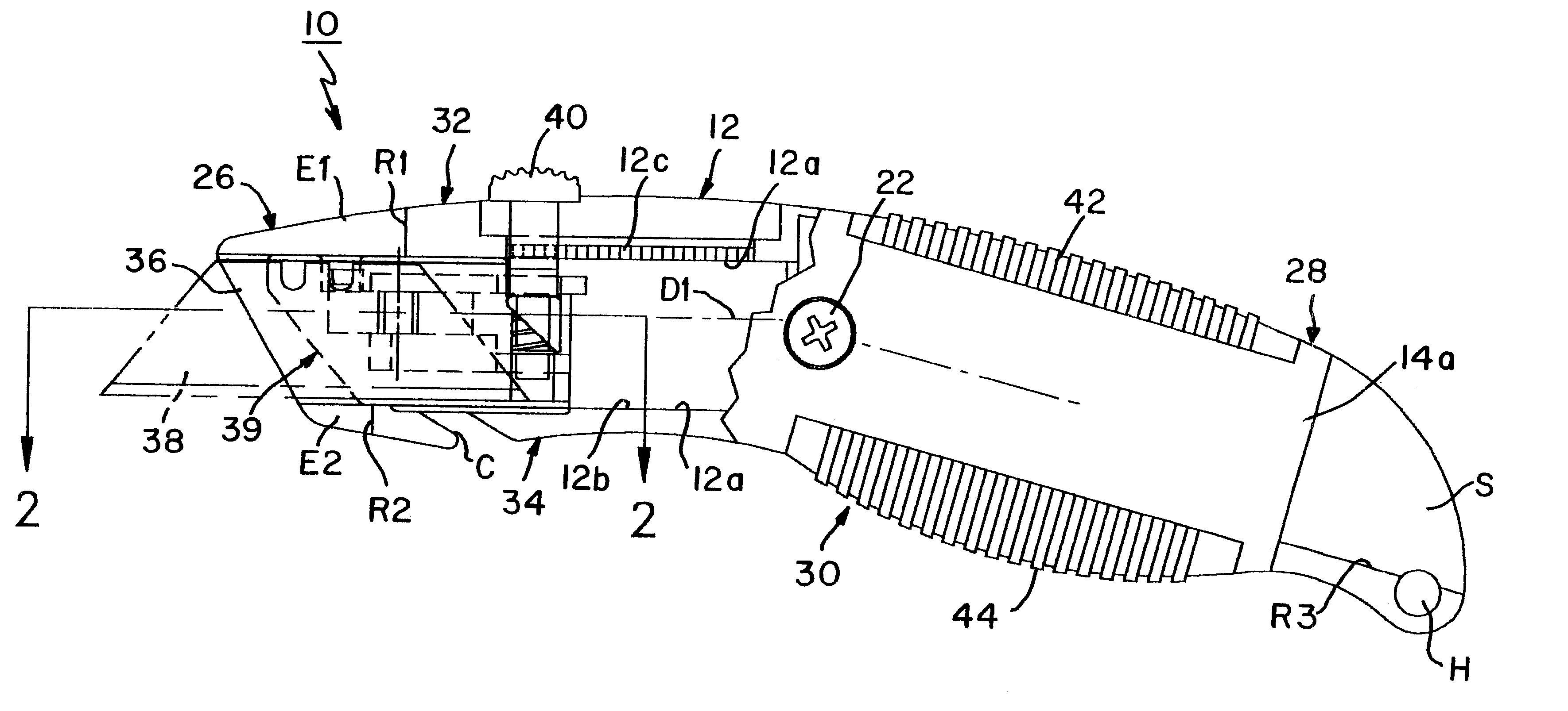
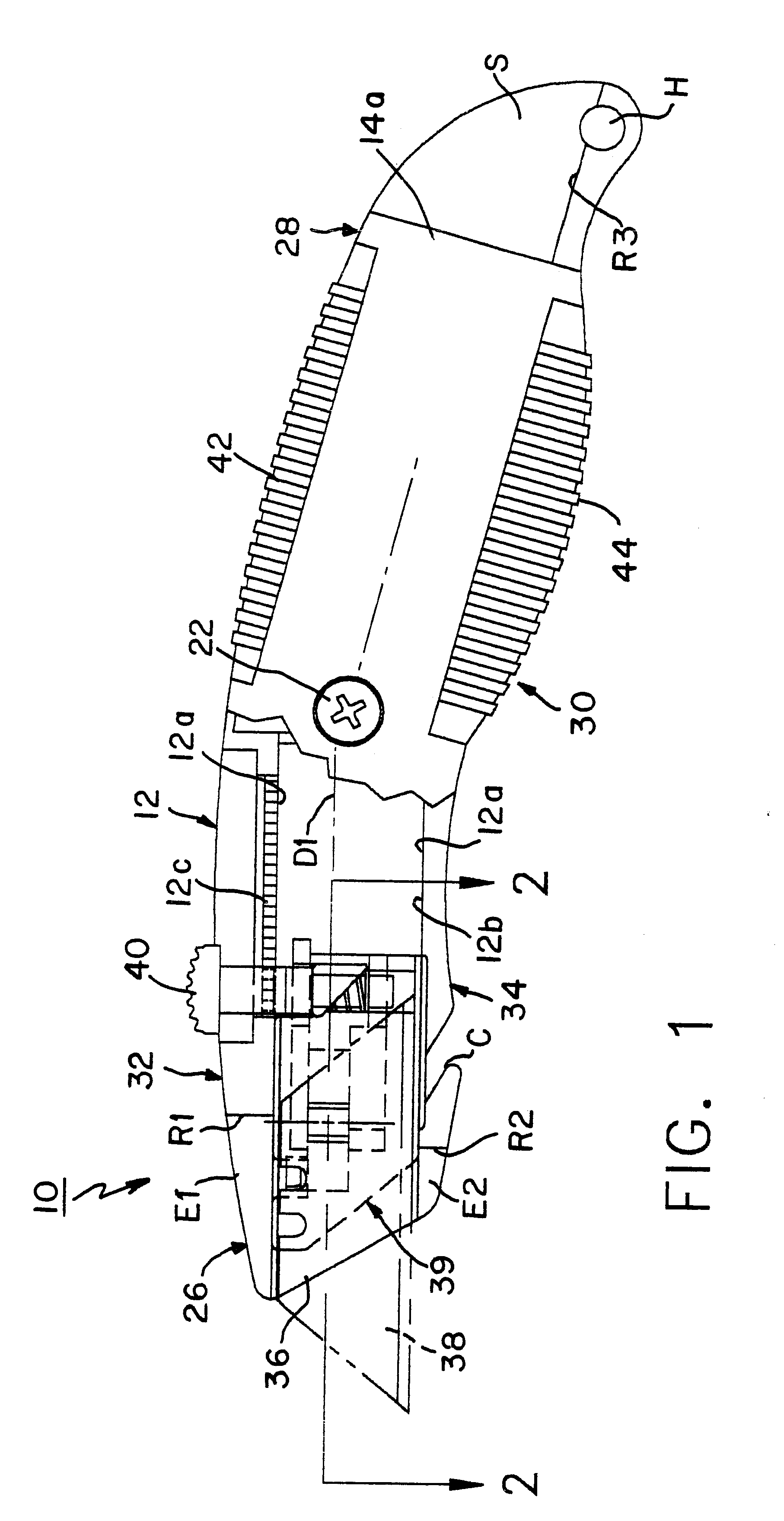
Referring now to the FIGS., in which identical or similar parts will be designated by the same reference numerals throughout, and first referring to FIG. 1, an adjustable safety utility knife in accordance with the present invention is generally designated by the reference numeral 10.

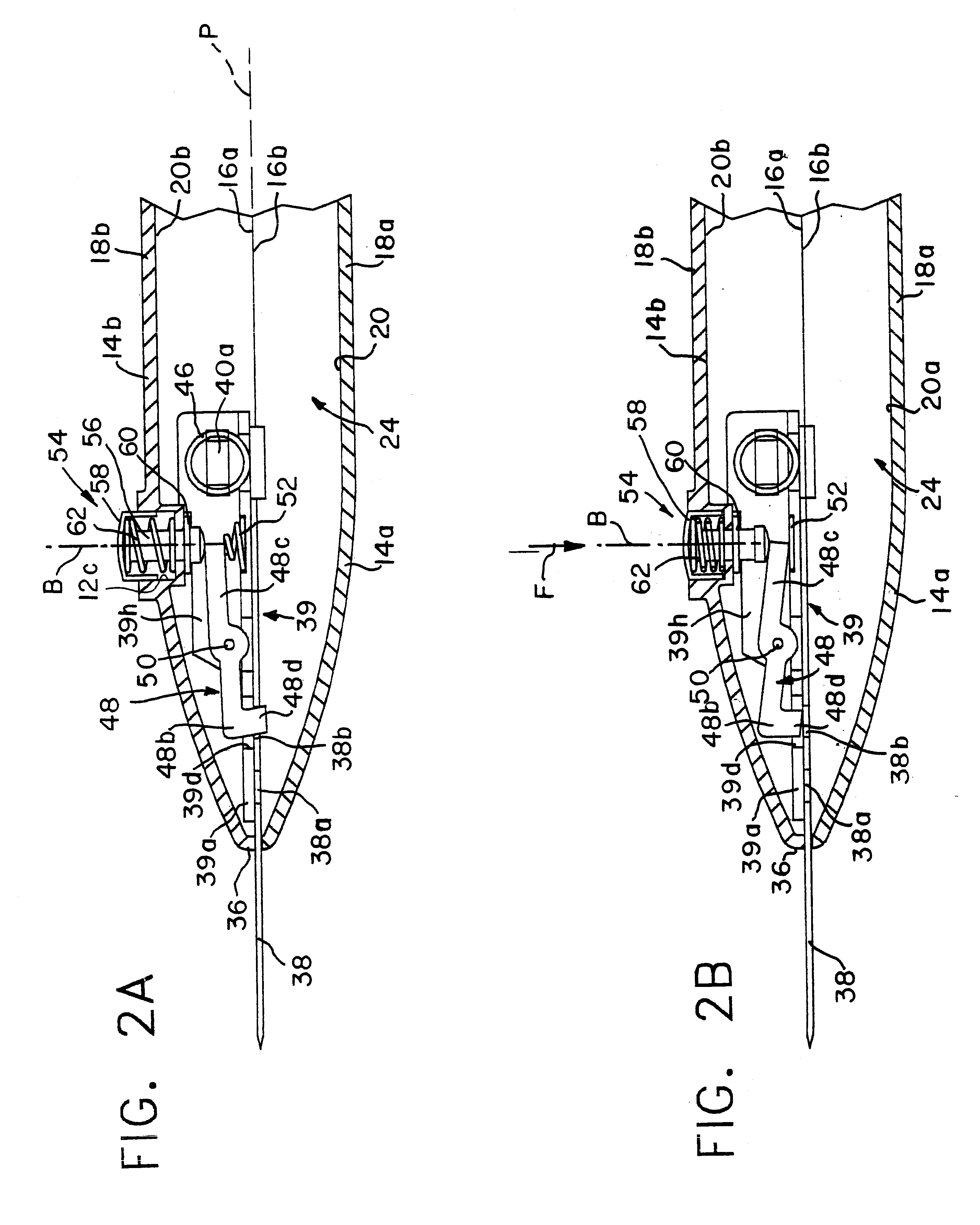
The utility knife 10 includes an elongated ergonomically shaped handle 12 formed of two elongate shell members 14a, 14b, each having a peripheral edge 16a, 16b (FIG. 2), respectively, and outer, generally convex surface 18a, 18b and an inner generally concave surface 20a, 20b, respectively. A suitable fastener, such as a transverse screw 22 (FIG. 1) is provided for fastening the shell members 14a, 14b to each other at the peripheral edges 16a, 16b (FIGS. 2A, 2B) along a vertical parting plane P (FIG. 2) to form an elongated internal cavity or compartment 24. The handle 12 defines a front end 26, a back end 28 and an intermediate portion 30 suitable to be gripped by the user, and also defining top and bo...


PUM


Abstract

An adjustable safety utility knife includes an elongated ergonomically shaped handle formed of two elongate shell members each having a peripheral edge and an outer generally convex surface and an inner generally concave surface. The shell members are fastened at the peripheral edges along a vertical parting plane to form an elongated internal cavity. The handle defines a front end, a back end and an intermediate portion suitable for being gripped by a user and also defining top and bottom surfaces extending along opposite sides of the shell members along the peripheral edges. The handle has a slot-like aperture at the front end substantially aligned with the parting plane and dimensioned for passage of a flat cutting blade therethrough. A guide element within the elongated cavity guides the cutting blade between a first position for safely storing the blade fully inside the cavity and a second position for selectively extending the blade beyond the aperture to expose at least a portion thereof. A manually operated button is arranged on the top surface and coupled to the guide element for selectively moving the blade between the first and second positions. The guide element includes a carriage within the elongated internal cavity for supporting a flat cutting blade and guide elements on at least one of the inner generally concave surfaces for guiding the carriage and cutting blade carried thereby between the first and second positions. The carriage includes a locking element for normally locking a cutting blade mounted thereon to substantially fix the cutting blade against relative longitudinal movements between the cutting blade and carriage. The locking element includes an unlocking element the actuation of which releases the cutting blade to permit relative longitudinal movements between the cutting blade and the carriage. A blade release element on one of the shell members actuates the unlocking element when manual force is applied thereto, whereby application of a force on the release element releases the cutting blade and enables it to be withdrawn through the front end aperture.

Description

1. Field of the InventionThe present invention generally relates to hand tools and, more specifically, to a front-loading adjustable safety utility knife with safety utility knife with safety quick-release lock.2. Description of the Prior ArtUtility knives are widely used in construction, business and hobby applications for cutting such materials as paperboard, wallboard, string and other objects. Commonly, such utility knives are in the form of an elongate hollow housing that can be gripped by the user along an intermediate portion thereof and into which there are placed trapezoidal flat cutting blades. The blades typically have a single cutting edge. The blade is typically slidably mounted on a carrier for movement between a retracted position within the housing and an extended position in which the cutting edge is at least partially exposed through a front end aperture or slot, the carrier being coupled to a manually operated element, such as a button positioned in a manner conve...

Claims


Application Information

Patent Timeline
IPC IPC(8): B26B5/00
CPCB26B5/001
Inventor KHACHATOORIAN, ZAREHPING, QUI JIAN
Owner OLYMPIA IND
Why Eureka
Try Eureka