Parking lock for a vehicle having an electrical drive, and an electrical drive for a vehicle

a technology of electrical drive and parking lock, which is applied in the direction of motor/generator/converter stopper, dynamo-electric converter control, braking system, etc., can solve the problem that the parking brake cannot completely prevent the vehicle, the selection of a low gear for producing the braking effect to supplement the parking brake cannot be produced, and the parking lock has not yet been provided

Inactive Publication Date: 2002-03-26
ZF FRIEDRICHSHAFEN AG
View PDF2 Cites 19 Cited by
  • Summary
  • Abstract
  • Description
  • Claims
  • Application Information

AI Technical Summary

Benefits of technology

The parking lock according to the invention also allows vehicles having an electrical drive to be provided with a simple and cost-effective with a braking system which protects the vehicle from rolling away inadvertently--preferably in addition to a conventional parking brake.
The electrical component of the parking lock is preferably activated only below a specific vehicle speed, which is preferably less than or equal to 5 km / h. As has already been stated above, this prevents the stator windings from being inadvertently short-circuited above a speed at which such activation of the electrical component could be dangerous.

Problems solved by technology

A problem with known parking brakes in terms of safety is that in some cases the parking brake cannot completely prevent the vehicle from rolling away inadvertently, particularly when said vehicle is located on a grade.
However, when the vehicles includes an internal combustion engine and an automatic transmission, the selection of a low gear for producing the braking effect to supplement the parking brake cannot be produced because of the torque converter that is present in the automatic transmission.
No separate parking lock has yet been provided for vehicles with an electrical drive.
In fact, electrical drives are subject to different problems relating to the possible use of parking locks, in particular when, as described above, the aim is to use parking locks with a ratchet wheel and a toothed catch.
Due to the high torques and the rotor inertia, very high forces are produced by the sudden stop in rotation which are not damped as easily as in the configuration having an internal combustion engine and automatic transmission.
Accordingly, conventional commercially available parking locks can not be used since they would not be adequate for withstanding the occurring loads and would be damaged very quickly.
However, both of these solutions necessitate a large installation volume and would have a very high intrinsic weight, which is a major disadvantage, particularly in automobile construction.
Furthermore, parking locks of such a design are considerably more expensive.
Furthermore, the development of appropriately modified parking locks for the electrical drive of a vehicle would involve a major time penalty and design effort.
Since the high torque peaks and reductions to be compensated for occur only during the latching-in process, and thus only very briefly, the use of parking locks designed for these maximum loads would not be acceptable financially, for the reasons stated above.
However, the torque peaks which occur in this case have already been dissipated by the prior braking of the rotary movement of the electrical drive train via the electrical component.
Furthermore, it is also intended to be impossible for it to latch in above a specific speed such as, for example, at speeds of 8 km / h or more.
This is an installation point at which relatively low speeds and relatively high torques occur.
As has already been stated above, this prevents the stator windings from being inadvertently short-circuited above a speed at which such activation of the electrical component could be dangerous.

Method used


Image

  • Parking lock for a vehicle having an electrical drive, and an electrical drive for a vehicle
  • Parking lock for a vehicle having an electrical drive, and an electrical drive for a vehicle
  • Parking lock for a vehicle having an electrical drive, and an electrical drive for a vehicle

Examples


Embodiment Construction

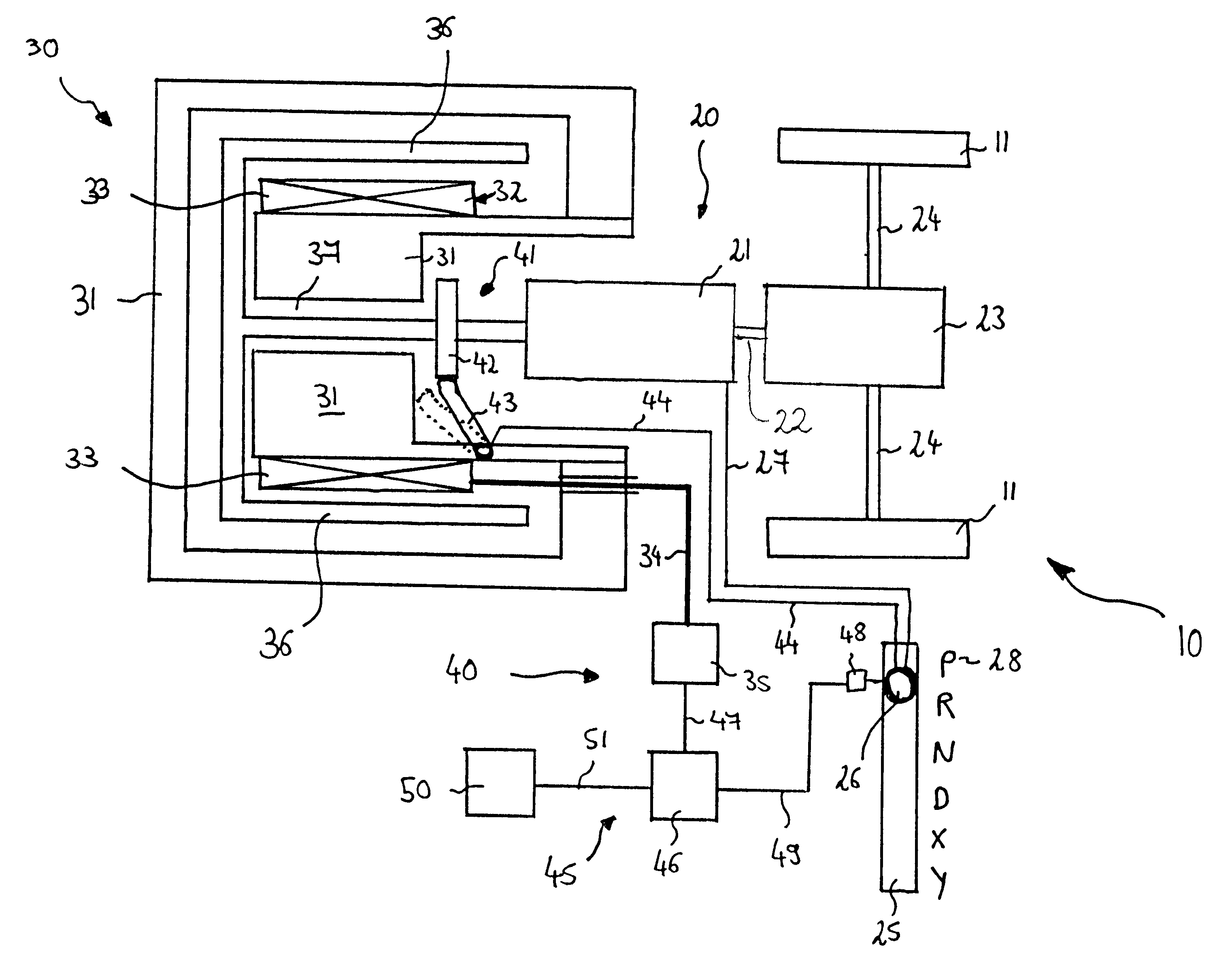
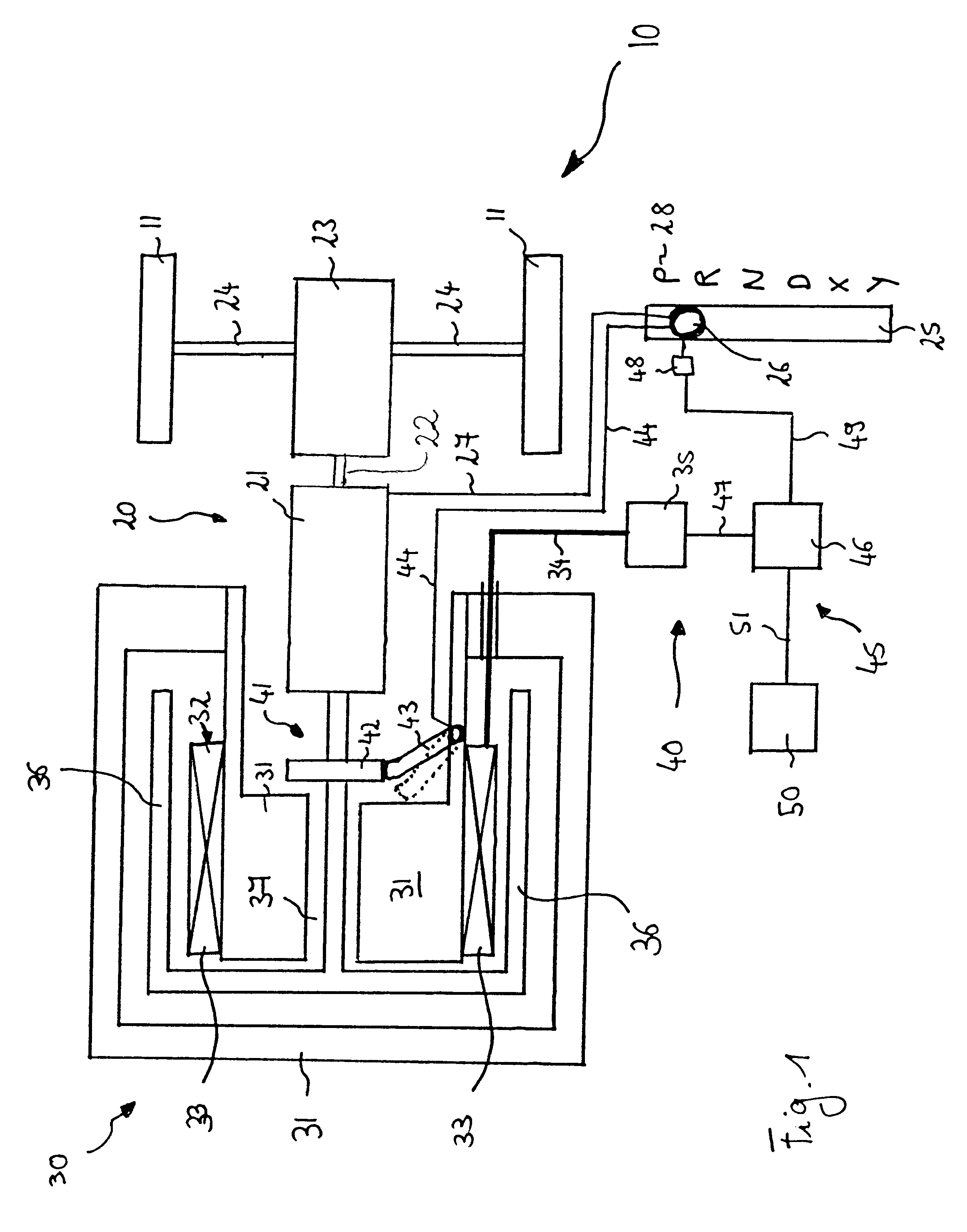
FIG. 1 is a schematic diagram of a front-wheel-drive motor vehicle 10 according to an embodiment of the present invention. In the interests of brevity and clarity, only those components which are relevant in the context of the present invention are shown. Furthermore, the individual components have not been drawn to scale.

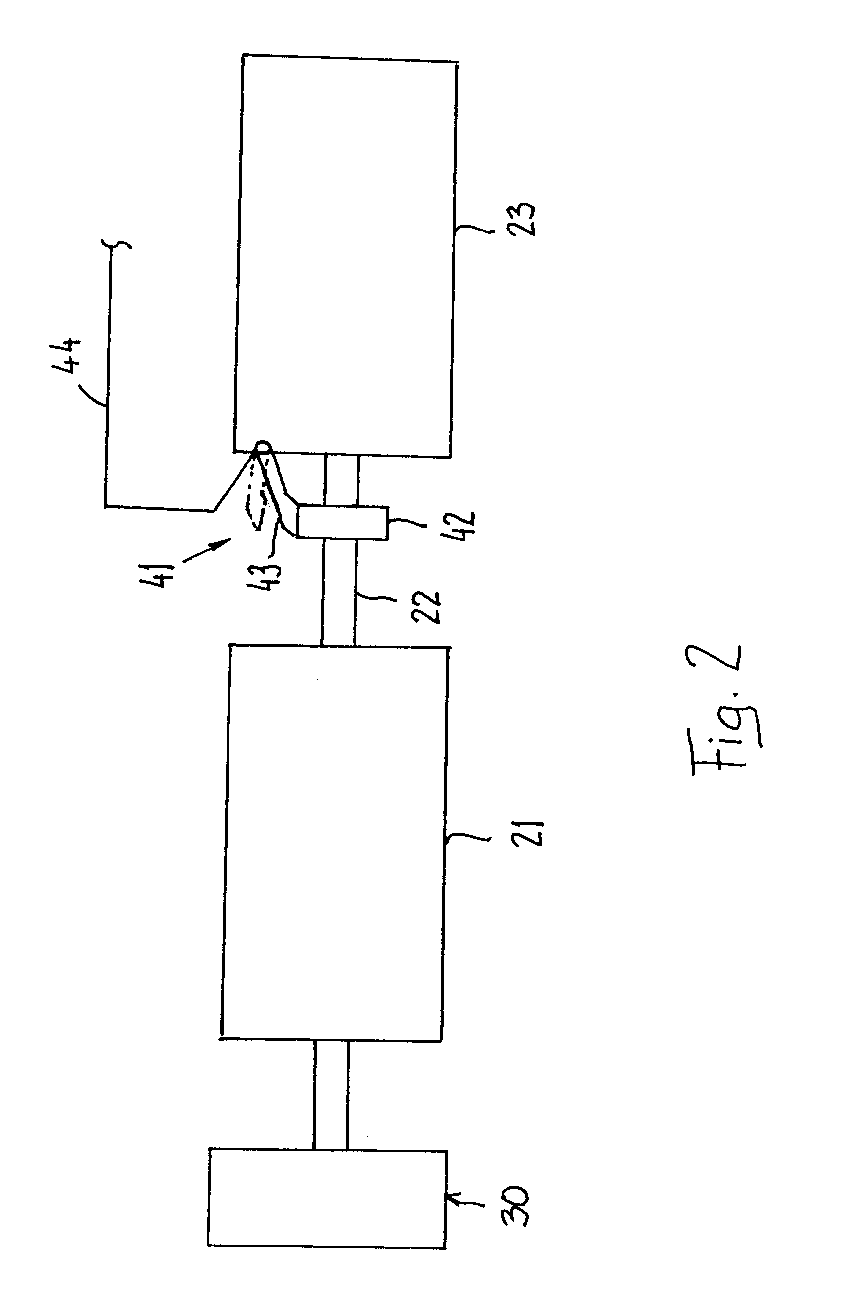
The vehicle 10 comprises a drive train 20 which produces and transmits the drive torque to drive the vehicle 10. To produce the drive torque, the drive train 20 includes an electrical machine 30 in the form of a synchronous machine with permanent-magnet excitation that is operatively connected to a transmission 21 which may, for example, comprise an epicyclic transmission. The transmission 21 is coupled to a differential 23, which then transmits the drive torques via axles 24 to two wheels 11 of the vehicle 10.

The electrical machine 30 is designed with a multi-part housing 31 in which an external rotor 36 and a stator 32 are arranged. A plurality of stator windings...


PUM


Abstract

A parking lock for a vehicle having an electrical drive train including an electric machine with a rotor, a stator having a plurality of stator windings, and power electronics for controlling the electric machine, and a transmission prevents the vehicle from rolling away inadvertently. The parking lock has a mechanical component which is mechanically operatively connected to the rotor when the parking lock is operated to stop rotation of this rotor. The mechanical component has a ratchet wheel and a toothed catch. Furthermore, the parking lock has an electrical component designed such that it produces a short-circuit in the stator windings, at least temporarily, when it is intended to operate the parking lock. When the parking lock is operated, the electrical component is thus activated in a specific time interval before operation of the mechanical component. The short-circuit in the stator windings produces a severe braking torque, which brakes the rotor. The time interval between activation of the electrical component and the activation of the mechanical component allows the rotor to be braked before the mechanical component is activated. In this way, the high torque peaks which occur when the rotor is being stopped are reduced by the electrical component, so that a mechanical component of relatively small size may be used.

Description

1. Field of the InventionThe present invention relates to a parking lock for a vehicle having an electrical device, and to a method for operating such a parking lock. The present invention also relates to an electrical drive for a vehicle.2. Description of the Related ArtMotor vehicles such as passenger vehicles have a parking brake for preventing the vehicle from rolling away inadvertently when the vehicle is parked. A problem with known parking brakes in terms of safety is that in some cases the parking brake cannot completely prevent the vehicle from rolling away inadvertently, particularly when said vehicle is located on a grade.For this reason, it is desirable to use a parking lock in addition to the parking brake. The parking lock is intended to make it impossible for the vehicle to roll away inadvertently at any time and in any place. In particular, the parking lock is designed to prevent the vehicle from rolling away when the vehicle is parked on a grade.When the vehicle inc...

Claims


Application Information

Patent Timeline
Patent Type & Authority Patents(United States)
IPC IPC(8): B60L15/20B60T1/00F16H63/00F16H63/48B60L7/24B60T1/06F16H61/22F16H61/28
CPCB60L7/003B60L15/20F16H63/48B60T1/005B60L2240/30Y10T477/393Y02T10/7275Y10T477/37Y02T10/64Y02T10/72
Inventor RODER, MANFREDOPPITZ, HORST
Owner ZF FRIEDRICHSHAFEN AG
Why Eureka
Try Eureka