
Fuel cell having water permeability adjustment capability

a fuel cell and water permeability technology, applied in the field of fuel cells, can solve the problems of overly moist solid polymer membrane, uneven moistening of solid polymer membrane, and dry solid polymer membran

Inactive Publication Date: 2002-04-02
SANYO ELECTRIC CO LTD
View PDF6 Cites 87 Cited by
  • Summary
  • Abstract
  • Description
  • Claims
  • Application Information

AI Technical Summary

Problems solved by technology

In fact, however, the solid polymer membrane is not evenly moistened, i.e., the solid polymer membrane is overly moist or dry in some parts.
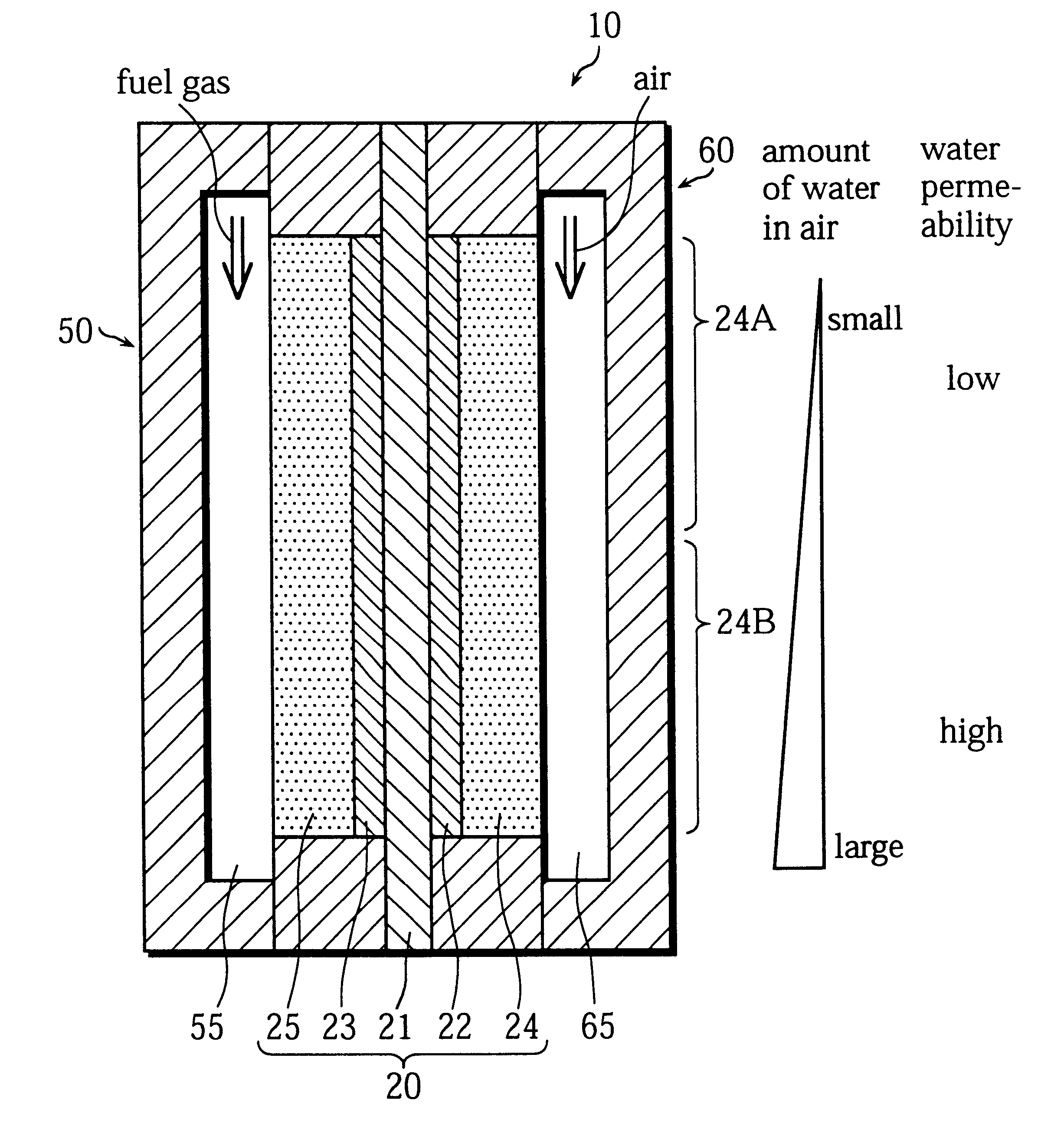
Especially, in the dry-air-type fuel cell, a large amount of water is dissipated from the solid polymer membrane at the entrance of the oxidizer, so that the solid polymer membrane tends to dry in this part.
As a result, the humidity of the oxidizer increases and it becomes more difficult to dissipate water into the gas as the oxidizer travels from the entrance through the exit.
In this case, however, the solid polymer membrane is overly moist at the exit, so that high electricity generation performance cannot be obtained.
In this case, however, the oxidizer is not evenly distributed across the cathodes and the concentration polarization is large in the electrode reaction, so that the power output is lowered.
This is problematic phenomenon.
Working favorably when pure hydrogen is used as the fuel gas, the Pt catalyst may be poisoned and have lowered catalysis when carbon monoxide is included in the fuel gas.
On the other hand, the cathode catalyst layer is overly moist at the exit for air, so that sufficient gas permeability cannot be obtained.
When the specific surface area of the carbon material is small, the water absorbency of the capillary attraction of the micropores among the carbon material powder is low, so that it is difficult for water to move through the micropores.

Method used


Image

  • Fuel cell having water permeability adjustment capability
  • Fuel cell having water permeability adjustment capability
  • Fuel cell having water permeability adjustment capability

Examples


example 6

Practical Example 6

The cell unit 100 is manufactured in the same way as the practical example 5. The amount of the PTFE-dispersed solution having the weight percentage of 60 wt % that is mixed with 10 g of carbon black powder having the specific surface area of 700 to 800 m.sup.2 / g is set as 7.0 g when generating the mixed paste for the water permeable part in the process 3.

example 7

Practical Example 7

The cell unit 100 is manufactured in the same way as the practical example 5. In this case, instead of the carbon black powder having the specific surface area of 700 to 800 m.sup.2 / g, carbon black powder having the specific surface area of 200 to 300 m.sup.2 / g is used when generating the mixed paste for the water permeable part in the process 3.

example 8

Practical Example 8

The cell unit 100 is manufactured in the same way as the practical example 5. In this case, instead of the carbon black powder having the specific surface area of 100 to 150 m.sup.2 / g, carbon black powder having the specific surface area of 200 to 300 m.sup.2 / g is used when generating the mixed paste for the water permeation suppressing part in the process 4.


PUM


Abstract

The object of the present invention is to provide fuel cell including a cell that is formed by sandwiching solid polymer membrane between an anode and a cathode that generates electricity with stability and high performance by evenly moistening the solid polymer membrane. For this purpose, in a gas diffusion layer 24, which is positioned adjacent to a cathode catalyst layer 22, the content of fluororesin in an area on the side of the entrance for the oxidizer is set to be higher than in another area on the side of the exit so that the water repellency in the entrance side area is higher than in the exit side area. As a result, a water permeation suppressing part 24A, where the water permeability is relatively low, is formed in the area on the entrance side, while a water permeable part 24B, where the water permeability is relatively high, is formed in the area on the exit side.

Description

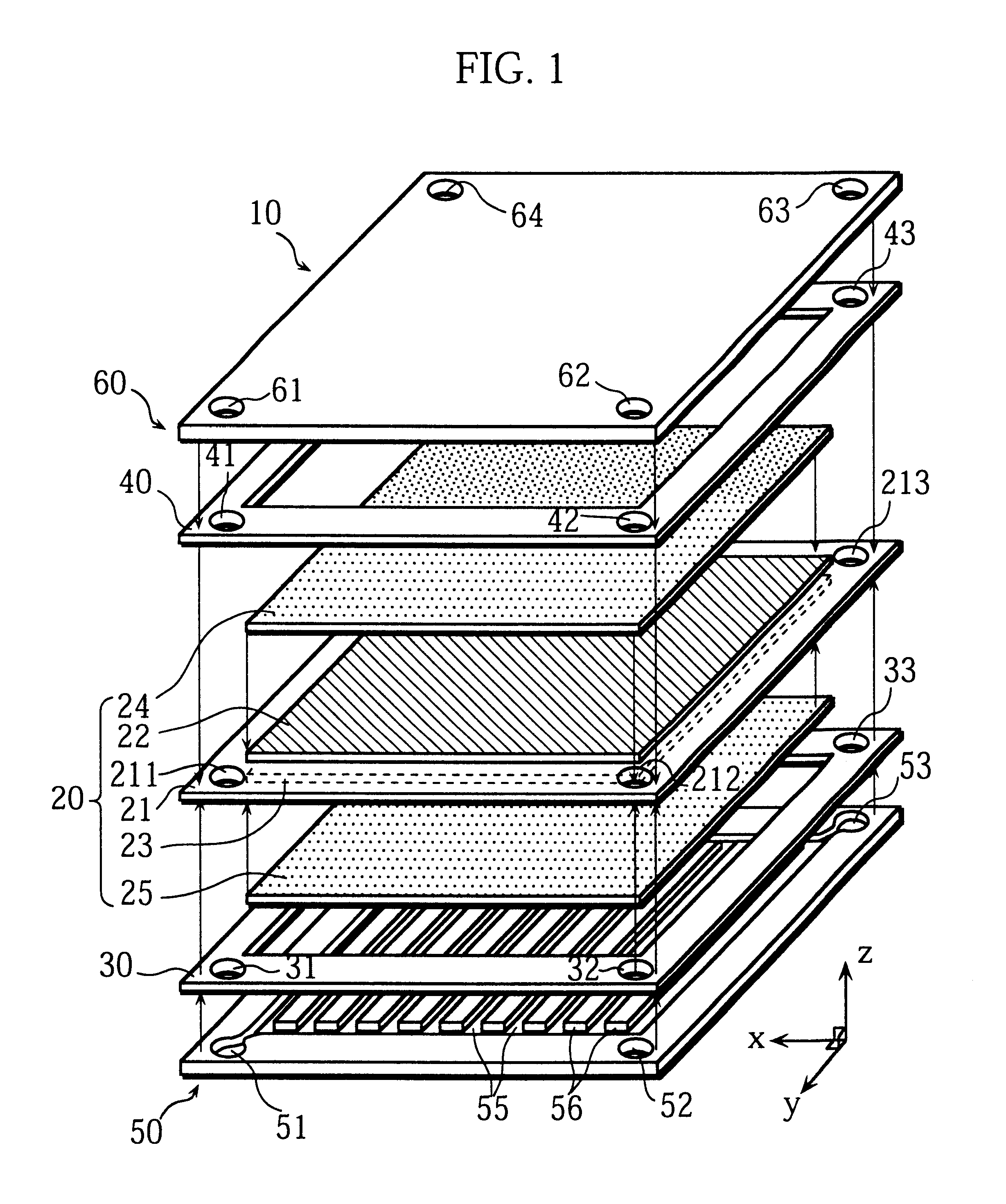
(1) Field of the InventionThe present invention relates to a fuel cell in which the solid polymer membrane is used as the electrolyte film.(2) Related ArtThe fuel cell is a cell that generates electricity by supplying hydrogen-rich fuel gas to the anode and oxidizer gas to the cathode and by electrochemically reacting hydrogen and oxygen. As the oxidizer, air is generally used. On the other hand, as the fuel gas, pure hydrogen gas, reformed lower alcohol, or reformed light hydrocarbon such as reformed natural gas and reformed naphtha is used.There are a variety of fuel cells according to the kinds of the electrolyte, for instance, the phosphoric acid type fuel cell and molten carbonate fuel cell. Especially, the fuel cell in which the solid polymer membrane is used as the electrolyte film has been recently under development.The basic structure of this type of fuel cell is as follows. A cell is formed by disposing a cathode on one side of a solid polymer membrane and an anode on the ...

Claims


Application Information

Patent Timeline
IPC IPC(8): H01M8/04H01M8/10
CPCH01M8/04291H01M8/1002Y02E60/521H01M8/1007Y02E60/50
Inventor ISONO, TAKAHIROMIYAKE, YASUOHAMADA, AKIRAKANEKO, MINORUNAKATO, KUNIHIRO
Owner SANYO ELECTRIC CO LTD
Learn More