
Thermal transfer image receiving sheet

Inactive Publication Date: 2002-04-02
DAI NIPPON PRINTING CO LTD
View PDF3 Cites 9 Cited by
  • Summary
  • Abstract
  • Description
  • Claims
  • Application Information

AI Technical Summary

Benefits of technology

Accordingly, an object of the present invention is to solve the above problems of the prior art and to provide a thermal transfer image receiving sheet that, when used with various printers, can be carried with improved accuracy, can form an image without misregistration, can prevent a trace of a spike of a metallic roller in the printer from reaching the image receiving face and hence can form an image having quality not significantly influenced by the trace of the spike.
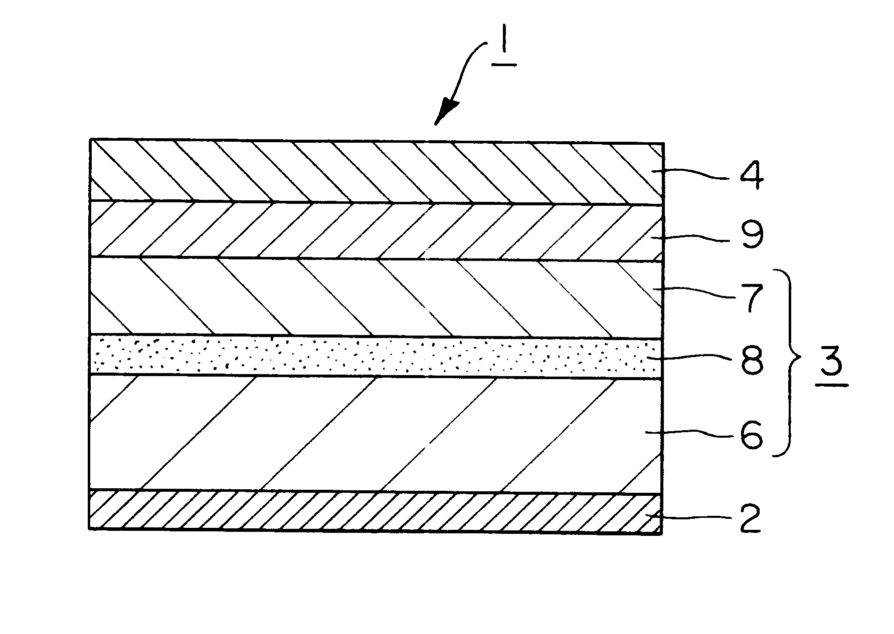
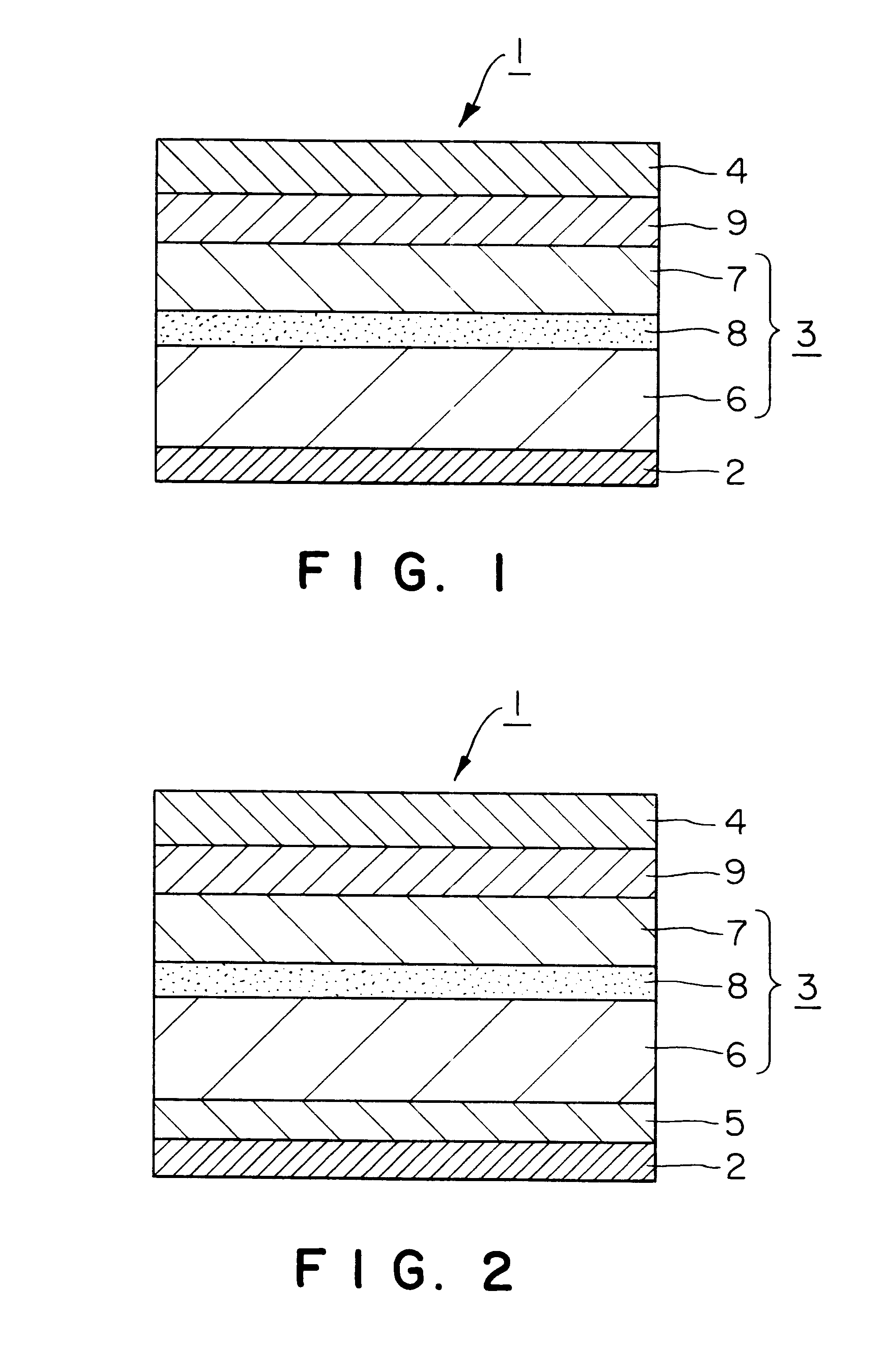
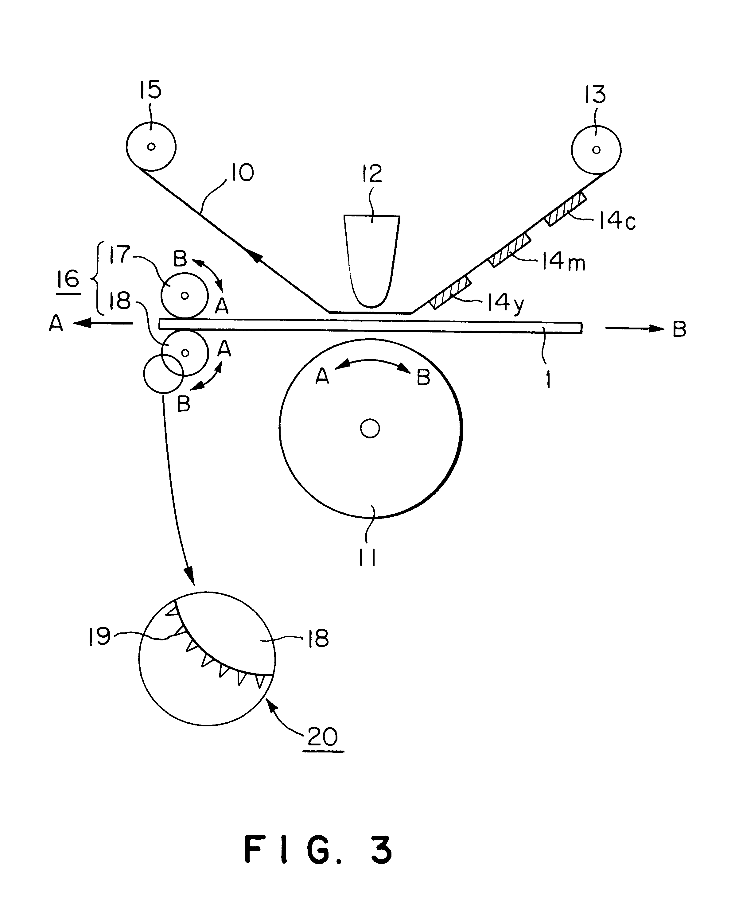
Formation of a grip layer using an unstretched synthetic resin layer having a softening point of 110.degree. C. or above, preferably an unstretched polyolefin resin layer, most preferably an unstretched polypropylene resin layer, in combination with the provision of a polyethylene resin layer between the grip layer and the substrate can prevent the spike 19 from passing through the thermal transfer image receiving sheet 1 and can improve the print quality. In addition, this arrangement can improve the biting by the spike 19 and hence is very effective for preventing the misregistration.

Problems solved by technology

This method, however, suffers from problems including that, due to the nature of reciprocation of the thermal transfer image receiving sheet, the paper positioning accuracy is so low that the so-called misregistration is likely to occur, and, in addition, it is difficult to realize a reduction in size and cost of the image printer.
This printer, however, is disadvantageous in that the mechanism is complicated and, hence, the size of the printer should be increased, it is difficult to form an image on a thermal transfer image receiving sheet of small size, and the price of the printer is high.
Before carrying accuracy is discussed, this type of printer has a drawback that, when the thermal transfer image receiving sheet is delivered, it is likely to be jammed within the printer.
Therefore, the carrying accuracy of a printer using this grip roller is not very good, and printing of an image while reciprocating the thermal transfer image receiving sheet has been likely to create misregistration.
In this case, however, the spike of the metallic roller bites the thermal transfer image receiving sheet, creating and leaving a trace of the spike.
In particular, in the case of a thin thermal transfer image receiving sheet, the trace of the spike poses a serious problem.
In some cases, the trace reaches the image receiving face on the surface of the thermal transfer image receiving sheet, resulting in deteriorated print quality.
Supplying a wide variety of thermal transfer image receiving sheets compatible with respective various printers, however, results in remarkably increased development cost and production cost.
Further, an increase in thickness of the thermal transfer image receiving sheet in order to reduce the influence of the spike limits the thickness and layer construction suitable for conventional thermal transfer image receiving sheets, often leading to restriction of functions commonly possessed by the thermal transfer image receiving sheet, for example, handle, nerve, gloss and other properties.

Method used


Image

  • Thermal transfer image receiving sheet
  • Thermal transfer image receiving sheet
  • Thermal transfer image receiving sheet

Examples


example 2

In the thermal transfer image receiving sheet of Example 1, the following polyethylene resin layer was formed between the substrate and the grip layer. The resin for the grip layer was the same as that used in Example 1. A high-density polyethylene resin was used for the polyethylene resin layer. In this case, the grip layer and the polyethylene resin layer were formed by coextrusion lamination through a multi-manifold head so as to give a total thickness of 33 .mu.m. At that time, the thickness of the polyethylene resin layer was 14 .mu.m, while the thickness of the grip layer (unstretched polypropylene resin layer) was 19 .mu.m. Other conditions were the same as those in Example 1. Thus, a thermal transfer image receiving sheet of Example 2 was prepared.

Polyethylene resin layer

High-density polyethylene resin (Jayrex LZO 139-5)

example 3

The procedure of Example 1 was repeated, except that the thickness of the microvoid film constituted by the microvoid layer was changed to 35 .mu.m, the grip layer was formed using an unstretched synthetic resin layer of the following medium-density polyethylene resin in a thickness of 33 .mu.m on the coated paper (127.9 g / m.sup.2) as the support by extrusion lamination. Thus, a thermal transfer image receiving sheet of Example 3 was prepared.

Grip layer

Medium-density polyethylene resin (Sumikathene L5721, manufactured by Sumitomo Chemical Co., Ltd.)

example 4

The procedure of Example 2 was repeated, except that the basis weight of the coated paper as the support was changed to 157 g / m.sup.2. Thus, a thermal transfer image receiving sheet of Example 4 was prepared.


PUM

PropertyMeasurementUnit
Angleaaaaaaaaaa
Softening pointaaaaaaaaaa
Timeaaaaaaaaaa

Abstract

A thermal transfer image receiving sheet is provided which, when used with various printers, can be carried with improved accuracy, can form an image without misregistration, can prevent a trace of a spike of a metallic roller in the printer from reaching the image receiving surface and hence can form an image having quality not significantly influenced by the trace of the spike.The thermal transfer image receiving sheet 1 comprises a substrate 3, a receptive layer 4 provided on at least one side of the substrate 3, and a grip layer 2 provided on the other side of the substrate 3. In this case, the grip layer 2 is constituted by an unstretched synthetic resin layer having a softening point of 110° C. or above. This constitution permits a spike of a metallic roller in a printer to satisfactorily bite the unstretched synthetic resin layer having a softening point of 110° C. or above as the grip layer 2. This prevents slippage between the metallic roller and the thermal transfer image receiving sheet 1 at the time of a reciprocation for image formation and hence can prevent misregistration. Therefore, the thermal transfer image receiving sheet can be carried with improved accuracy, and a thermally transferred image can be formed without misregistration.

Description

This invention relates to a thermal transfer image receiving sheet for use in a thermal transfer system wherein a thermal transfer image receiving sheet is superposed on a thermal transfer sheet and a colorant is thermally transferred from the thermal transfer sheet onto the thermal transfer image receiving sheet to form an image on the thermal transfer image receiving sheet, and a process for producing the same. More particularly, the present invention relates to a thermal transfer image receiving sheet capable of preventing misregistration which is likely to occur in the formation of an image on a thermal transfer image receiving sheet, and a process for producing the same.Formation of letters or images on an object by a thermal transfer system has hitherto been carried out in the art. A thermal dye transfer system (a thermal sublimation transfer system) and a thermal ink transfer system (a hot melt transfer system) have been extensively used as the thermal transfer system. The th...

Claims


Application Information

Patent Timeline
IPC IPC(8): B41M5/44B41M5/40B41M5/00B41M5/50B41M5/382B41M5/52
CPCB41M5/44Y10S428/914Y10S428/913B41M5/52B41M2205/32
Inventor KOMETANI, SHINJI
Owner DAI NIPPON PRINTING CO LTD
Learn More