Method for beam welding of hardenable steels by means of short-time heat treatment

a technology of heat treatment and hardenable steel, which is applied in the direction of laser beam welding apparatus, heat treatment process control, electric beam welding apparatus, etc., can solve the problems of inability to plastically mitigate the high transient stress occurring, the disadvantage of conventional welding methods in welding speed, component distortion, unit cost and after-treatment expense, and the effect of relatively low heating speed

Inactive Publication Date: 2002-04-02
FRAUNHOFER GESELLSCHAFT ZUR FOERDERUNG DER ANGEWANDTEN FORSCHUNG EV +1
View PDF8 Cites 16 Cited by
  • Summary
  • Abstract
  • Description
  • Claims
  • Application Information

AI Technical Summary

Benefits of technology

The present invention uses a transient temperature field and a method to produce it which can be readily integrated into processes and which is adaptable even for hardenable steels with relatively high critical cooling times and relatively deep welding seams. The entire welding seam has has an adequately low cooling speed and the normalized or tempered basic structure of the initial state outside the welding zone and the heat affected zone is not damaged.
Leakage of the air from inside closed hollow parts through the joining gap can be prevented, although the pressure of the air is increased by the preheating. Thus, very good welding seam quality is achieved without additional vent holes, which are often undesirable and require additional production expense, and hose pores reaching all the way to the surface of the welding seam are avoided.
Necessary hardening or tempering treatments possibly following the welding operation may be integrated into the heat treatment cycle of the welding by using simple process technology and optimum utilization of energy.

Problems solved by technology

Carbon steels with a carbon content of C.gtoreq.0.25% and low-alloy steels with carbon contents of C.gtoreq.0.20% are only weldable to a limited extent by commercial means, as the increased hardening in the welding and heat affected zone caused by the carbon and by various alloy elements results in cracks.
The hardening and subsequent crack formation occurs through the formation of martensite or lower bainite, which are only slightly deformable, and slightly (or not at all) self-annealed, which are incapable of plastically mitigating the high transient stresses occurring during cooling.
However, for many components, in particular mass-produced components, conventional welding methods have disadvantages with regard to welding speed, component distortion, unit costs, and after-treatment expense.
These shortcomings are from relatively low power densities, which result in relatively low heating speeds, relatively high introduction of heat, and large welding seam volumes.
However, such methods result in a higher hardening of the fusion heat affected zone, with a corresponding higher susceptibility to cracking of the welding seams.
The effects of these drawbacks are increased, in that conventional methods of bulk preheating can be integrated into automated beam welding systems only with difficulty.
Short cycle times are too expensive, and result in a deterioration of welding seam quality from oxidation of the joint.
This drawback is caused by extremely high quenching speed, which is clearly less than the t.sub.8 / 5 -times.
However, because of the use of high frequency, the process is restricted in application to thin metal sheets.
A drawback of this method is that it can be used only for thin metal sheets and only very limited for hardenable steel.
It is therefore not usable for power transmission elements or mechanically functional components.
The nature of the above drawback is that the superimposed temperature time cycle of the inductive post-heating cannot be adjusted, or at least cannot be adjusted for all depth zones, within the welding seam to the requirements necessary to avoid hardening with beam welding of hardenable steels.
Specifically, since the heating depth is not adjustable to the necessary welding seam depth, the cooling speed cannot be selected adequately small (or at least not for the entire welding seam depth).
The high peak temperature of the post-heating cycle therefore destroys the defined normalized or tempered structure.
Because the heating depth with the inductive application of energy is too little with a high frequency, heat energy is not introduced until after termination of the welding process.
Consequently, hardening occurs.
The high peak temperature of approximately 1000.degree. C., which is higher than the austenitizing temperature and which results from the relative heating depth which is slight with reference to the component thickness as well as the relatively high quenching speed resulting from the high feed rate leads moreover to the danger of new hardening even in regions outside the HAZ of the welding zone.

Method used


Image

  • Method for beam welding of hardenable steels by means of short-time heat treatment
  • Method for beam welding of hardenable steels by means of short-time heat treatment

Examples


Embodiment Construction

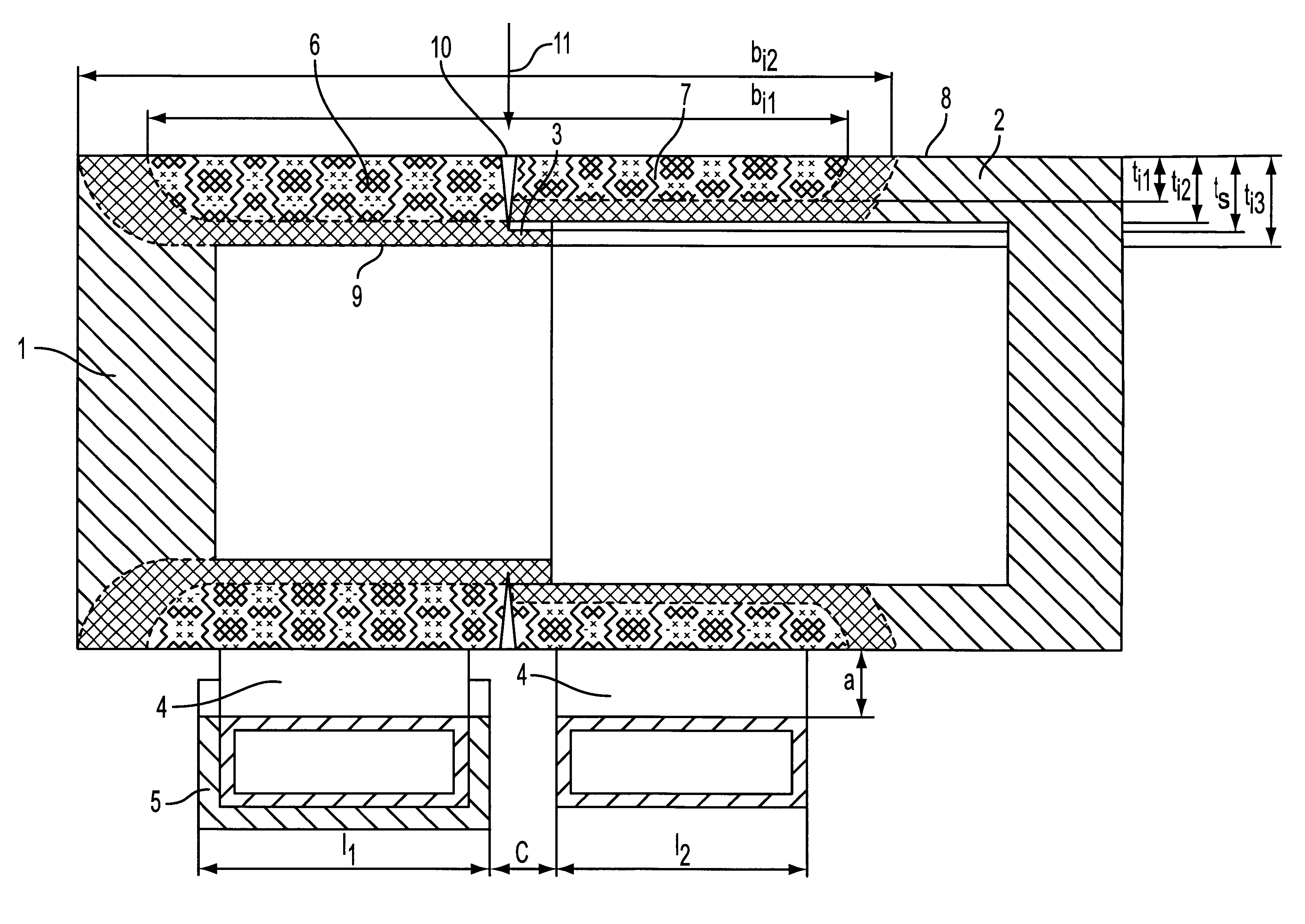
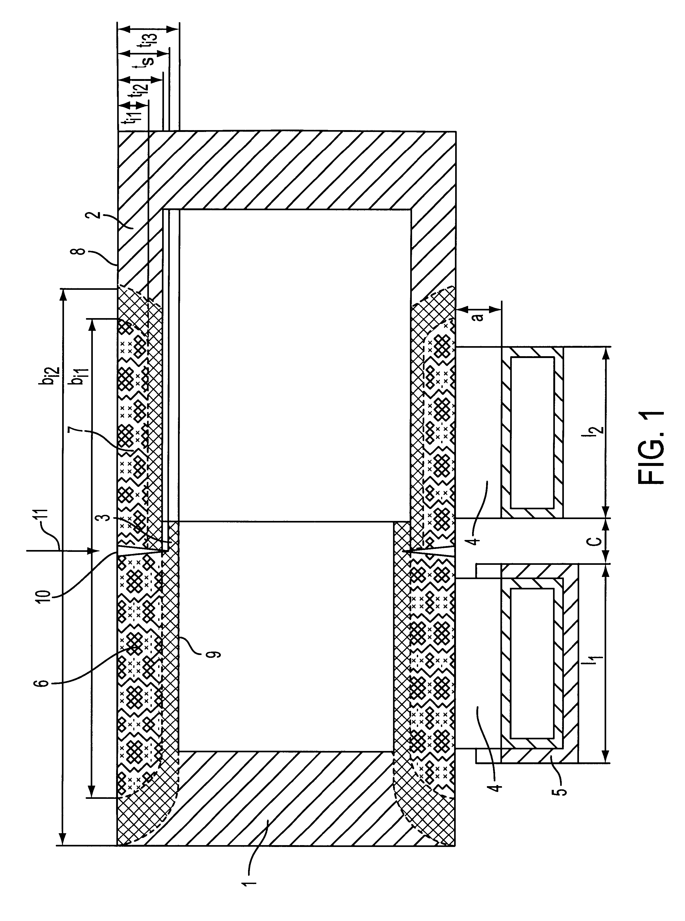
Two parts 1 and 2 are to be welded in to FIG. 1 with an axial circumferential seam. The external diameter of both parts is 45 mm. The inner diameter of part 2 is 35 mm. Part 1 is provided with seam support 3, which is 3 mm thick. The parts are joined with an overdimension from 0.05 to 0.13 mm. Both parts are made of C45 and are in the normalized state. Their hardness is 225 HV.sub.0.05.

An inductive introduction energy is selected as the preheating method. The induction frequency is 10 kHz. The inductor 4 is a double-winding half-shell inductor. Implementation as a half-shell inductor simplifies automated feeding and removal of the joined parts 1 and 2 into and out of the heating station. The inductor 4 has field amplification sheets 5 on the winding opposite part 1, which, despite the greater wall thickness of the part 1, provides an average temperature T.sub.1 inside the inductive heating zone 6, which is higher than the average temperature T.sub.2 in the inductive heating zone 7. ...


PUM

PropertyMeasurementUnit
time τAaaaaaaaaaa
temperaturesaaaaaaaaaa
temperatureaaaaaaaaaa

Abstract

The invention concerns a method for beam welding of hardenable steels using a short-time heat treatment. A preferred area of application of the invention is motor vehicle and mechanical engineering. In the method according to the invention, the short-time heat treatment occurs first as the sole preheating in a defined manner, and then the beam welding begins after a defined cooling time, at the latest.

Description

1. Field of the InventionThe invention concerns the beam welding of engineering components made of hardenable steel. The invention is useful for all components joinable by beam welding methods, which components are subjected to mechanically, cyclically, or dynamically high loads. Because of a local wear load, these components consist at least partially of hardenable steels or which are hardened and annealed because of their high mechanical load. The invention can be used particularly advantageously for the production of extremely varied, in particular rotationally symmetric power transmission elements, pressure-exposed hollow parts, hydraulic rams, valves, etc. A preferred area of application of the invention is motor vehicle and mechanical engineering, primarily automotive engineering.2. Description of Background InformationCarbon steels with a carbon content of C.gtoreq.0.25% and low-alloy steels with carbon contents of C.gtoreq.0.20% are only weldable to a limited extent by comme...

Claims


Application Information

Patent Timeline
Patent Type & Authority Patents(United States)
IPC IPC(8): B23K26/00B23K15/00B23K26/42B23K26/20B23K26/32B23K103/04
CPCB23K26/421B23K15/0033B23K26/60
Inventor BRENNER, BERNDTGNANN, RUDIGER ARNOLDNAUNAPPER, DIETMARDUSCHEK, CARSTEN
Owner FRAUNHOFER GESELLSCHAFT ZUR FOERDERUNG DER ANGEWANDTEN FORSCHUNG EV
Why Eureka
Try Eureka