System and method for browsing graphically an electronic design based on a hardware description language specification

a hardware description and language technology, applied in the direction of instrumentation, program control, cad circuit design, etc., can solve the problems of limited communication of critical design information, inconvenient design definition of abstract design definitions at the rtl-level, and inconvenient design management for designers and tools

Inactive Publication Date: 2002-04-02
SYNOPSYS INC
View PDF9 Cites 112 Cited by
  • Summary
  • Abstract
  • Description
  • Claims
  • Application Information

AI Technical Summary

Benefits of technology

Preferably, user dynamically selects design entirely or partially for graphical presentation. Selected presentations are referred to herein as "views," such that each view is generated dynamically and may involve one or more instances of user-selected design objects, (e.g., components, pins, circuits, logic blocks, interconnects, signal nets, buses, annotating notes, etc.). During browsing of selected views, user may edit design objects or other functional or non-functional aspects thereof, preferably in connectivity-driven manner (i.e., editing is graphically sensitive to associated design connections.) In this interactive manner, presentation views of design are effectively more intuitive and illustrate design data to convey design intent more understandably, particularly for use in design documentation or other user communication.

Problems solved by technology

Although conventional graphical representations serve to illustrate certain design aspects, thereby effectively improving human communication, such graphical representations are, nonetheless, imprecise and informal, and often limited for communicating critical design information.
Moreover, prior to widespread use of computer graphics workstations, which have advanced display outputs and input devices, such graphical representations were employed primarily for manual human visualization purposes, i.e., without convenient means to enter design data into computers.
Furthermore, as recent system chip designs approach or exceed multi-million-gate counts, even relatively more abstract design definitions at the RTL-level may be difficult for designers and tools to manage, particularly since such large designs may be unacceptably detailed and too unwieldy for practical simulation runs.
Unfortunately, with conventional design verification or simulation methodologies, textual specification (i.e., languaged-based definition) of prototype circuit under development is commonly employed.
Hence, designers no longer "draw" schematics, with or without CAD-tool assistance.

Method used


Image

  • System and method for browsing graphically an electronic design based on a hardware description language specification
  • System and method for browsing graphically an electronic design based on a hardware description language specification
  • System and method for browsing graphically an electronic design based on a hardware description language specification

Examples


Embodiment Construction

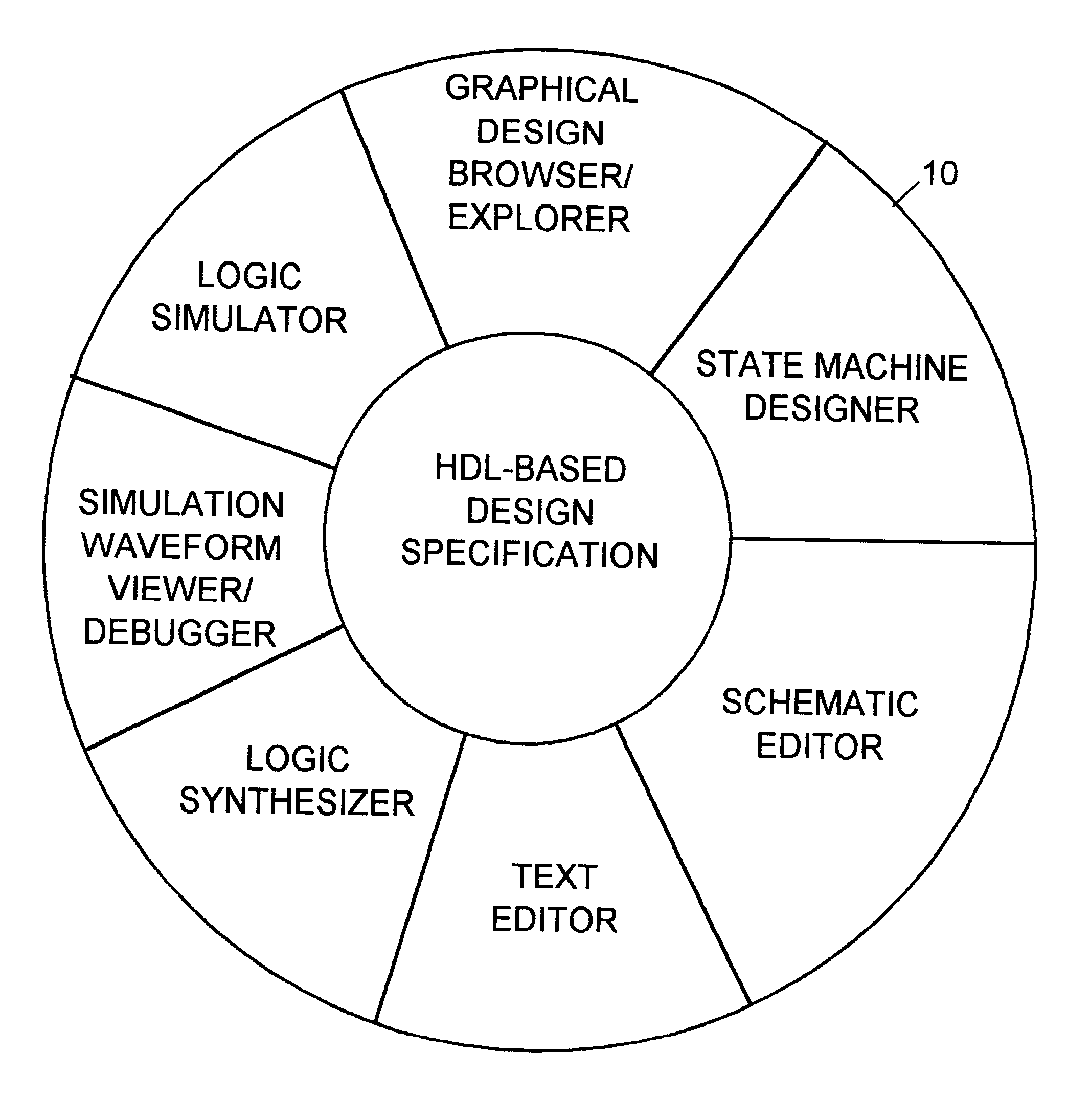
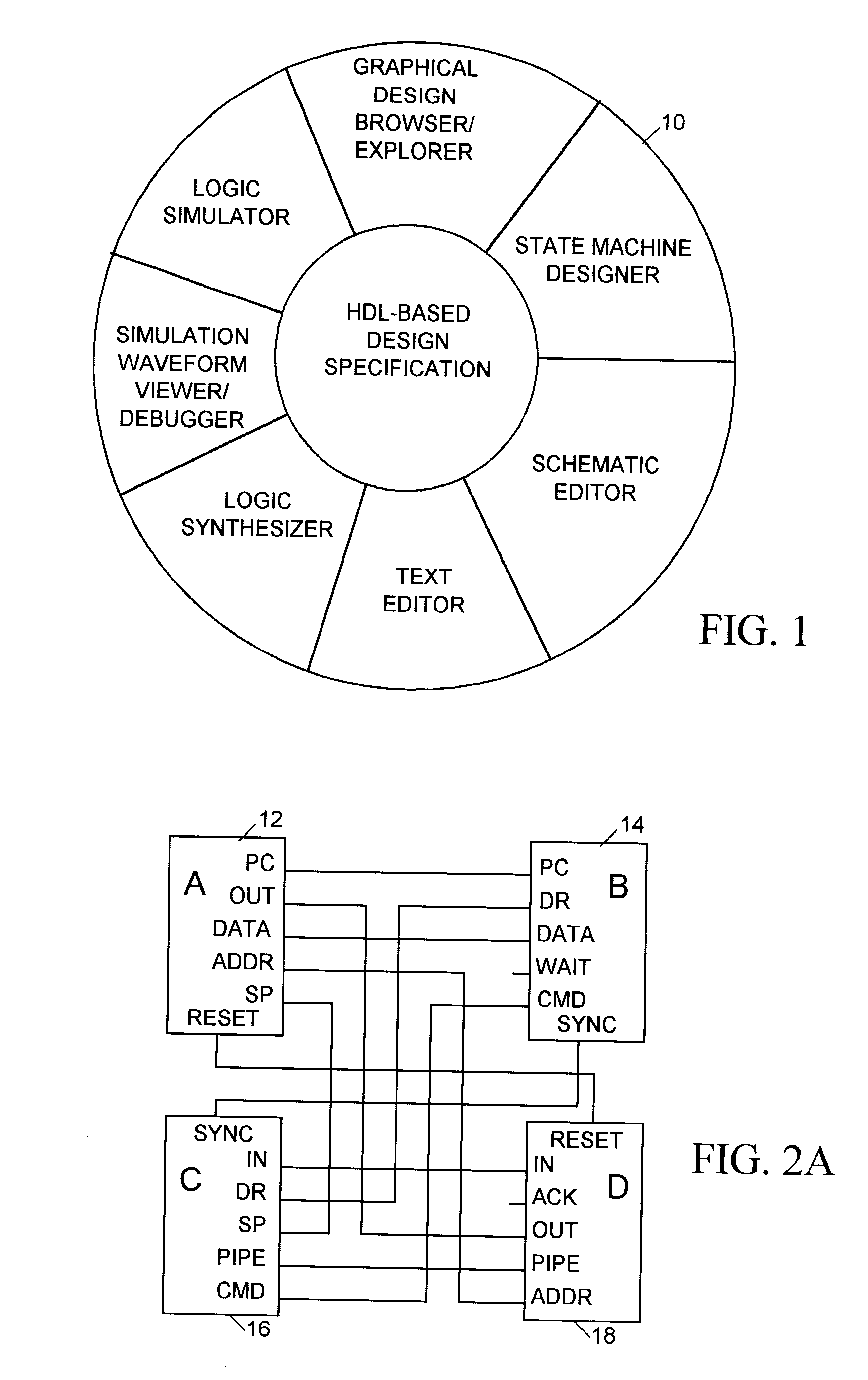
Preferred embodiment is a system and / or related method for enabling, among other things, selective browsing and editing of hardware description language (HDL)-based design. One or more computer-automated engineering or design software tools are described herein for graphically exploring one or more specified electronic designs.

Generally, when operating or executing on a computer or engineering workstation, present automated design tool or functionally equivalent program initially processes or compiles HDL or other fictionally equivalent specification of electronic circuit design or system (e.g., Verilog or VHDL-format or similar files), and automatically generates therefrom graphical database, which may include various design data, such as component instances, component pins, routing wires connecting such pins to symbolize signal nets, buses, design information, etc.

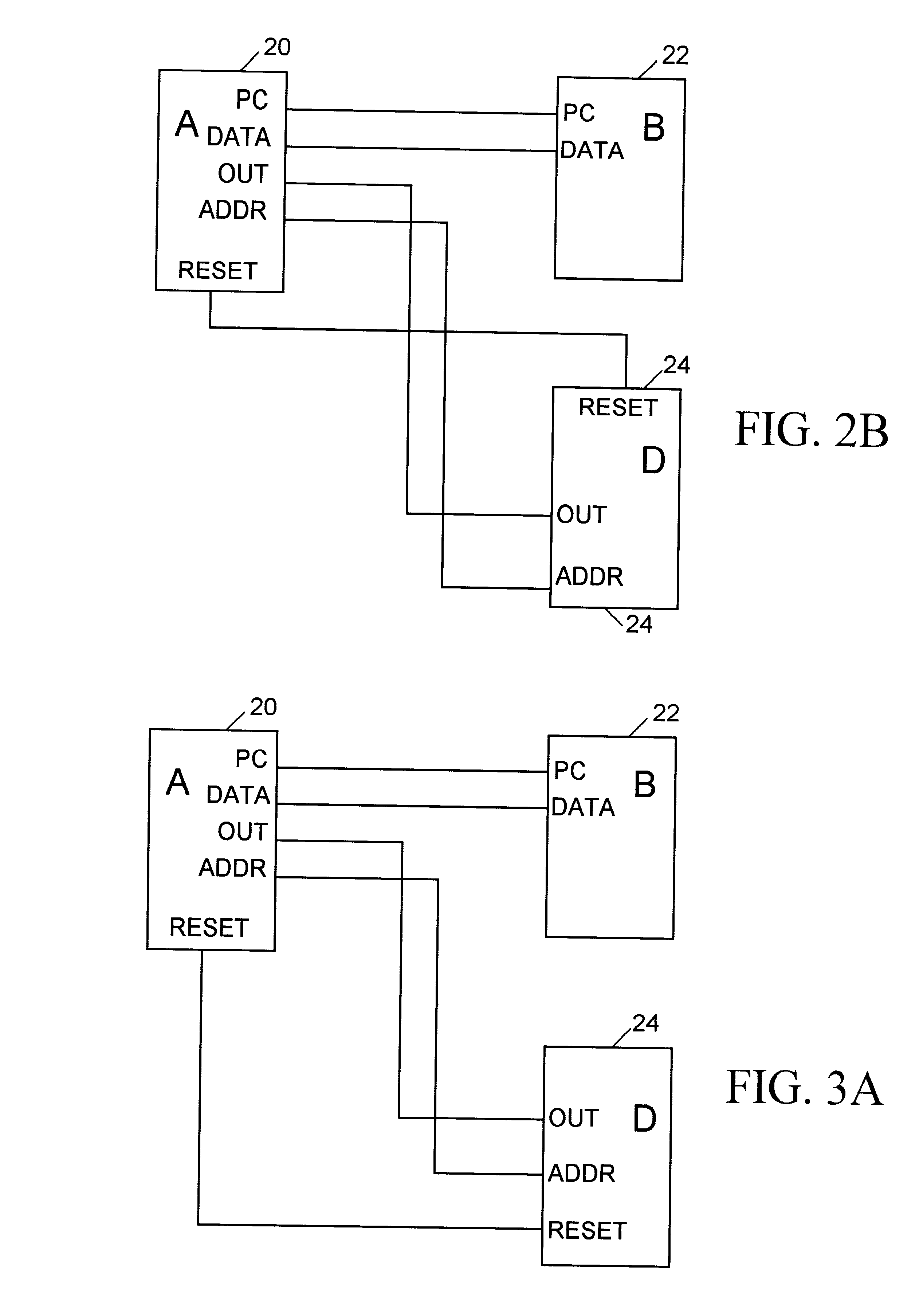
Additionally, user / designer may use such design tool dynamically to select or indicate, and graphically present or dis...


PUM


Abstract

Hardware description language (HDL)-centered design system and methodology uses HDL specification effectively as master depository for design intent or knowledge. Through network browser, designers conveniently navigate or explore design graphically. Designers selectively review or save design in entirety or portions. Design capture, analysis, and manipulation are based on HDL specification, either directly through text file editing, or indirectly through use of graphical tools.

Description

Invention relates generally to computer-aided design ("CAD") of electronic circuits, and more particularly to graphical visualization and exploration of electronic circuit designs specified in hardware description language ("HDL").BACKGROUND OF INVENTIONConventional electronic circuit design tools and methodology employ textual and / or graphical entry means to capture design intent, specify circuit behavior, and communicate design intent and behavior, particularly between original circuit designer and other technical personnel, such as design reader, potential user, or other design team members. CAD environments typically provide software-automated entry means to enable communications between designer and computer-implemented tool, i.e., to capture, analyze, or manipulate design data.Various graphical representation methods are used to facilitate human visualization and communication, such as: logic symbols, block diagrams, process flowcharts, finite state machine transition diagrams...

Claims


Application Information

Patent Timeline
Patent Type & Authority Patents(United States)
IPC IPC(8): G06F17/50
CPCG06F17/5045G06F30/30
Inventor LEE, CHIA HUEITSAI, JENSENCHEN, MENG-HUIHO, BANGHWAHUANG, YEN-SONTENG, CHANGSON
Owner SYNOPSYS INC
Why Eureka
Try Eureka