Diversion treatment method

a well and treatment method technology, applied in the direction of drinking water installation, borehole/well accessories, survey, etc., can solve the problems of inability to accept injected fluids, relatively low injectivity, and high cost of mechanical diversion techniques, so as to facilitate real-time analysis of down hole pressure, the effect of greater control of fracture dimensions or matrix penetration

Inactive Publication Date: 2002-04-09
OCEAN ENERGY RESOURCES +1
View PDF30 Cites 127 Cited by
  • Summary
  • Abstract
  • Description
  • Claims
  • Application Information

AI Technical Summary

Benefits of technology

Advantageously, by spotting a volume of diverting agent in the tubing/wellbore annulus across a desired treatment area of subterranean formation, the diversion agent may be squeezed or displaced into the desired treatment area of the subterranean formation prior to introduction of the treatment fluid through the tubing. Utilizing annular displacement of diversion agent into the formation in combination with displacement of well treatment fluid down the tubing allows focused placement of the treatment fluid by placing and repositioning the tubing in the wellbore, while at the same time monitoring the treating pressure to determine effectiveness of diversion. Advantageously, this allows real time modification of treating procedure in order to match the treatment to the response of the formation.
Further advantageously, maintaining a volume of diversion agent in the annulus above and adjacent to the formation being treated allows displacement of add

Problems solved by technology

Some intervals may possess relatively low injectivity, or ability to accept injected fluids, due to relatively low permeability, high in-situ stress, and/or formation damage.
However, conventional diversion techniques may be costly and/or may achieve only limited success.
In this regard, mechanical diversion techniques are typically complicated and costly.
Furthermore, mechanical diversion methods are typically limited to cased hole environments and depend upon adequa

Method used


Image

  • Diversion treatment method
  • Diversion treatment method
  • Diversion treatment method

Examples


example 1

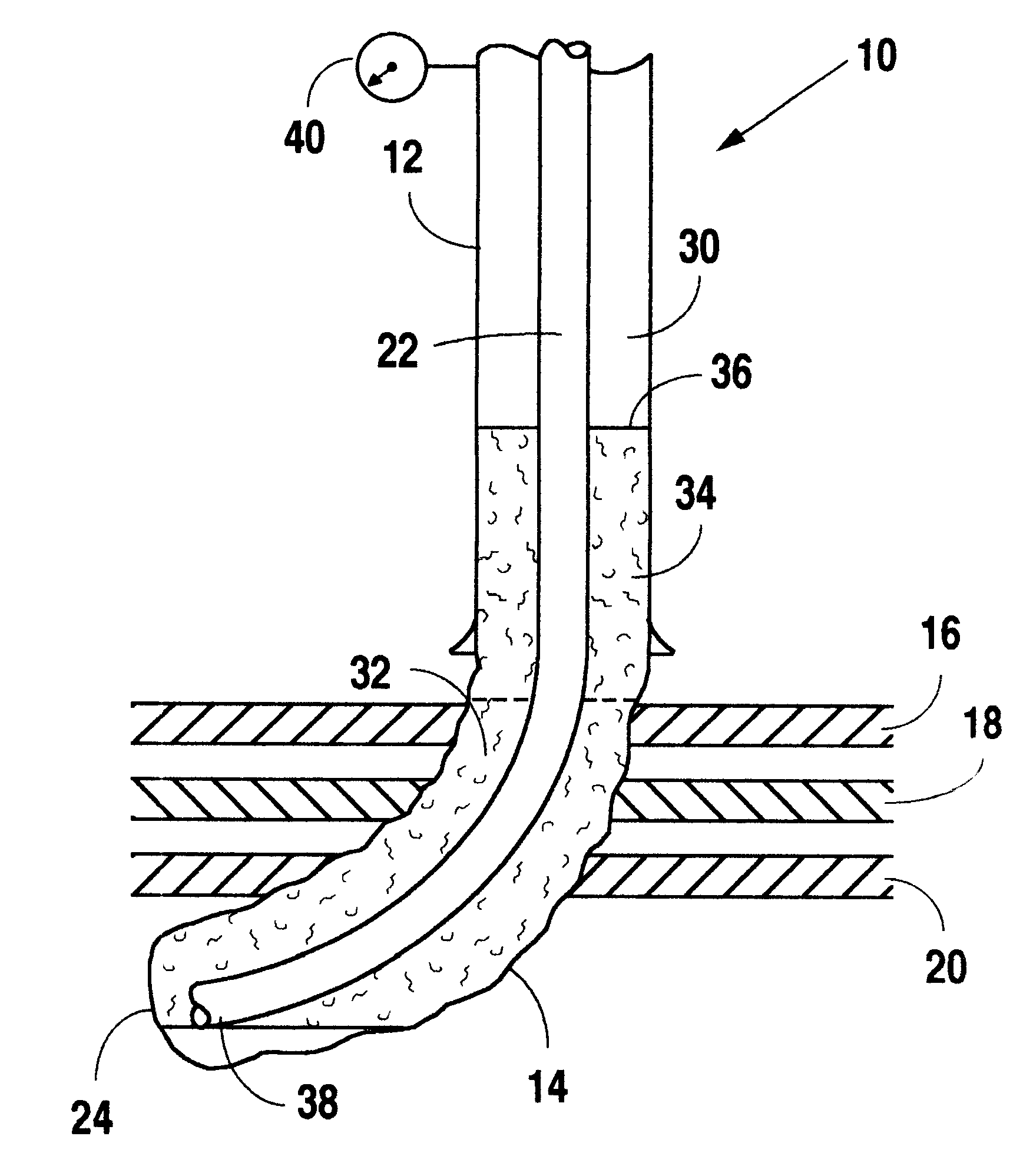
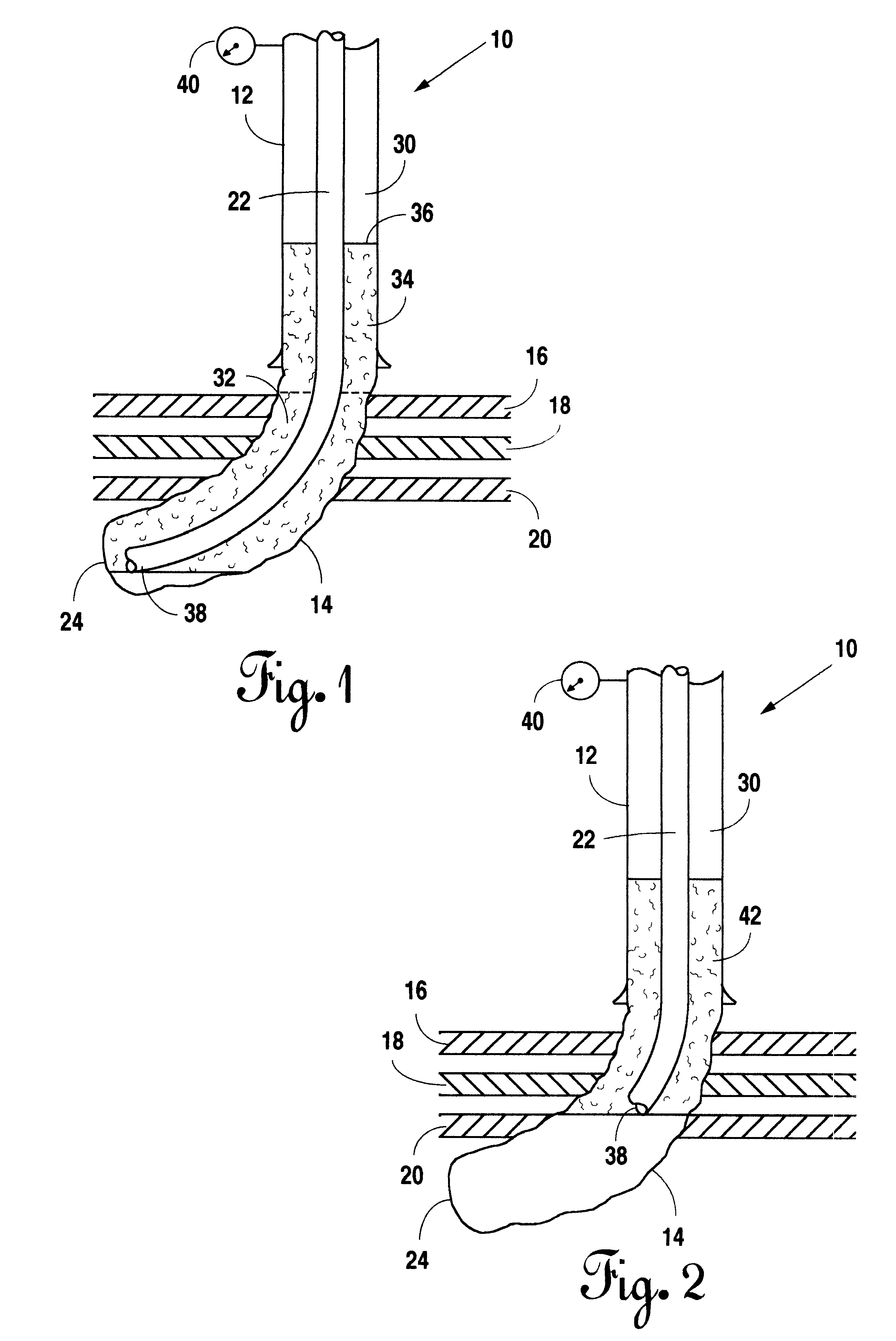
A subject well having a horizontal completion in the Nelson porosity of the Upper Mission Canyon formation was evaluated for treatment according to the disclosed method. The completion was in a low porosity interval (0.4%-10.1% porosity) with the permeability less than 1.12 md. Production in this interval was desired from natural vertical fractures which had been indicated in core samples. Acid stimulation was selected as the most promising method for introducing high conductivity channels to connect with the natural fracture mechanism. BJ Services' 3-dimensional acid frac model ("MACID") was utilized to model the treatment. The primary design criteria was to create a high conductivity path via small radial fractures while avoiding a conductive path into an adjacent formation known as the Midale. Table 1 gives reservoir data for the test well. Table 2 gives well configuration (including tubular geometry) for the completion. Table 3 illustrates calculated fluid volumes for the comple...

example 2

Salt was mixed with fresh water to achieve the desired density necessary to create a diversion system having a neutral buoyancy. In this regard, 10 grams of Divert X was added to the salt to perform the test. 100 millimeters of water was chosen as the test volume so that a 100 milliliter glass cylinder could be used to observe the floating or sinking of the Divert X material. One gallon per 1,000 ("GPT") NE-18 nonemulsifier was added to reduce surface tension in the water. The tests were mixed and observed in the glass cylinders for 20 minutes duration. The dry Divert X material is about 22 millimeters of volume in a 100 millimeter cylinder. Table 5 represents the results of these tests.

TABLE 5 Specific Gravity of Divert X Floating, Divert X Sinking, Carrier Fluid Milliliters of Material Milliliters of Material 1,000 2 18 1.010 4 17 1.020 8 14 1.030 10 12 1,040 10 10 1.050 20 2 1.060 22 0

Based on the above, the Divert X material did not all float or sink, indicating that the density...

example 3

Table 7 lists components of an acid well treatment fluid and diversion pad for the disclosed method.


PUM


Abstract

Methods and compositions for stimulating multiple intervals in wells by diverting well treatment fluids into multiple intervals by alternately displacing diverting agent from the annulus into a subterranean formation and displacing treatment fluid from a tubing string into the subterranean formation.

Description

BACKGROUND OF THE INVENTION1. Field of the InventionThis invention relates generally to methods and compositions for treating wells, and, more specifically to methods and compositions for stimulating multiple intervals in wells. In particular, this invention relates to methods and compositions for diverting well treatment fluids into multiple intervals by alternately displacing diverting agent from the annulus into a subterranean formation and displacing treatment fluid from a tubing string into the subterranean formation.2. Description of Related ArtWell treatments, such as acid and fracture treatments of subterranean formations are routinely used to improve or stimulate the recovery of hydrocarbons. In many cases, a subterranean formation may include two or more intervals having varying permeability and / or injectivity. Some intervals may possess relatively low injectivity, or ability to accept injected fluids, due to relatively low permeability, high in-situ stress, and / or formati...

Claims


Application Information

Patent Timeline
IPC IPC(8): E21B43/25
CPCE21B43/25E21B43/14
Inventor PURVIS, DONALD L.CRAMER, DAVID D.SMITH, DAVID D.WALTON, DOUGLAS L.
Owner OCEAN ENERGY RESOURCES
Why Eureka
Try Eureka