
Smoke evacuation apparatus

a smoke evacuator and smoke technology, applied in the field of smoke evacuator, can solve the problems of not being optimally efficient in the collection and removal of smoke and surgical debris from the surgical site, operating at less than maximum efficiency in the direction of surgical technique employed, and generating a great deal of smoke and other airborne particulate matter in the vicinity of the surgical site, so as to achieve the effect of efficient collection of smoke and debris and low cos

Inactive Publication Date: 2002-04-09
ACUDERM
View PDF11 Cites 24 Cited by
  • Summary
  • Abstract
  • Description
  • Claims
  • Application Information

AI Technical Summary

Benefits of technology

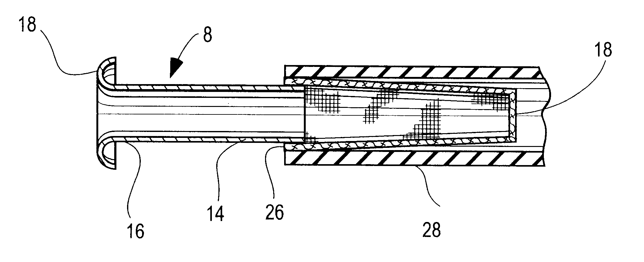
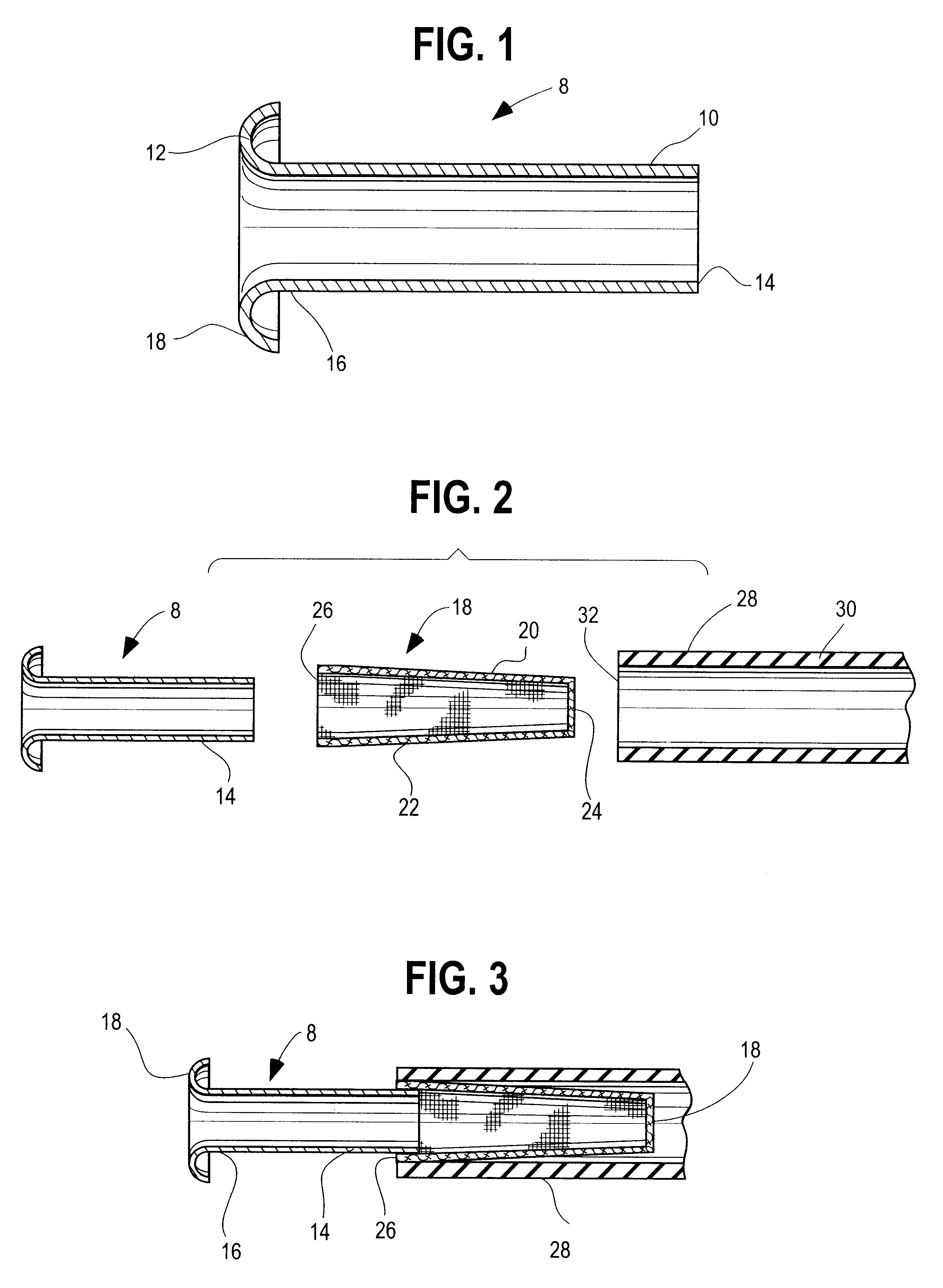
In the preferred embodiment, the flared horn nozzle portion is in the nature of a continuous annular lip integral with one end of the body portion. The lip includes a smooth curved surface which extends from the body portion exteriorly therefrom so that the lip includes a surface portion having a hemispherical cross-section so that the lip extends downwardly in a direction substantially parallel to the interior walls of the body portion. It has been found that the use of such a lip promotes a smooth laminar flow of a fluid stream containing smoke and surgical debris entrained therein from the environment of the surgical site into the body portion of the collector for removal of the smoke and surgical debris from the environment of the surgical site. Such lip configuration also serves to expand the field of influence thereby assuring the complete capture of smoke and debris.
Thus, in use, the collector can be connected to a source of reduced pressure to maintain the body portion at a reduced pressure whereby a fluid stream from the surgical site is drawn around the lip and into the body portion of the collector whereby smoke and surgical debris entrained in the fluid stream is removed from the surgical site. As the entrained smoke and surgical debris is drawn into the body portion of the of the collector, the filter positioned thereon serves to remove particulate matter and blood aerosols from the environment of the surgical site. It has been found that the collector of the present invention is simple and inexpensive to manufacture and use. In addition, it can be fabricated out of inexpensive materials and thus is disposable after use to avoid biohazard and contamination of subsequent surgical operations.

Problems solved by technology

In both electrosurgery and laser procedures, the surgical techniques employed generate a great deal of smoke and other airborne particulate matter in the vicinity of the surgical site.
One particularly successful example is the smoke evacuator described in U.S. Pat. No. 5,423,779 to Charles R. Yeh. While smoke evacuators like that described in the foregoing patent have received widespread acceptance, they may nonetheless operate at less than maximum efficiency in the collection and removal from the surgical site of smoke and surgical debris.
One of the reasons that smoke evacuator techniques heretofore used have not been optimally efficient is because the nozzle of the smoke evacuator, in most applications, must be located within approximately two inches of the surgical site.
Otherwise, there is a risk that substantial portions of the smoke and debris thus generated may dissipate into the atmosphere from the surgical site, posing health hazards to health care workers.
Indeed, such electrosurgery and laser surgery techniques, because they tend to disperse blood into an aerosol, leave behind such aerosols which can pose a health risk to anyone entering the theater of the surgical operation, even several hours after the surgery has been completed.
While the hyperbolic configuration is quite effective in removing smoke and surgical debris from the surgical site, it requires relatively close manufacturing tolerances.
In addition, the collector described in the foregoing patent does not include any means for filtering particular matter from the rapidly moving air stream.

Method used


Image

  • Smoke evacuation apparatus
  • Smoke evacuation apparatus

Examples


Embodiment Construction

Referring now to FIG. 1 is a detailed description of the smoke evacuator of the present invention, there is illustrated in that figure a collector 8 embodying the features of the present invention having generally cylindrical walls 10 and a flared horn nozzle portion 12, preferably integral therewith. The body portion of the collector of the present invention includes a distal end 14 adapted to be connected to a source of reduced pressure. As will be appreciated by those skilled in the art, the source of reduced pressure may be a vacuum pump or an exhaust fan to reduce the pressure within the body portion 10. Alternatively, the source of reduced pressure may also be a smoke evacuator of the type described in U.S. Pat. No. 5,243,779.

In accordance with the practice of the invention, the distal portion 16 of the body portion 10 includes a generally hemispherical lip 18 integral with the side walls of the body portion 10 defining a smooth arcuate surface extending from the proximal end ...


PUM


Abstract

This is directed to a smoke evacuator for use in electro surgery and laser surgery to collect smoke and surgical debris which includes body portion, a flared horn portion to promote flow of smoke and surgical debris into the body portion and a filter positioned on the body portion to remove particulate matter contained in the smoke and surgical debris.

Description

BACKGROUND OF THE INVENTIONThe present invention is directed to smoke evacuation apparatus, and more particularly to an improved collector for capturing smoke and other airborne debris generated in the course of electrosurgery and laser surgery.Electrosurgery and laser surgery are found in more widespread use, and particularly in many types of dermatologic, cosmetic and / or plastic surgery procedures. As is well known to those skilled in the art, electrosurgery may involve the use of electrically heated needles which may be used to burn tissue from the surgical site or may involve electrodesiccation and fulguration procedures in which an electric arc is generated between a needle and surgical site.By the same token, laser surgery is likewise gaining widespread acceptance in procedures in which a laser is used to burn and / or vaporize tissue from a surgical site. Such laser surgical techniques are becoming more widely used in a variety of dermatologic surgery operations. In both electr...

Claims


Application Information

Patent Timeline
Patent Type & Authority Patents(United States)
IPC IPC(8): A61M1/00A61B18/00
CPCA61B18/00A61M1/00A61B2218/008
Inventor YEH, CHARLES R.
Owner ACUDERM
Learn More