Implementation system for continuous welding, method, and products for the implementation of the system and/or method

a technology of continuous welding and implementation system, applied in the direction of weld torches cleaning, manufacturing tools, liquid cleaning, etc., can solve the problems of deterioration of strength and quality of welds, disturbed flow of inert gas to welds, and accumulation of dust, so as to improve the length of continuous operation

Inactive Publication Date: 2002-04-09
WELD AID PRODS
View PDF21 Cites 11 Cited by
  • Summary
  • Abstract
  • Description
  • Claims
  • Application Information

AI Technical Summary

Benefits of technology

Various methods and / or systems are disclosed for providing an improved welding system and / or method that substantially improves the length of time of continuous operation for an automated welding system between maintenance shutdowns. One of the disclosed method steps or system elements provides for dipping a welding nozzle [28 or 28a] and a portion of its related diffuser into a bath [12 or 12a] of fluid each time the automated welding system moves through a welding cycle. A product that may best accomplish this step or element is also disclosed.Another method step or system element may include the removal of spatter accumulation via an electromagnetic field that magnetically pulls the spatter without direct contact with the nozzle or diffuser. A further disclosed method step or system element includes lubrication of the continuous electrode used for welding, and may include a step prior to lubrication that involves cleaning the continuous electrode prior to adding lubricant. The steps may vary as to whether or not they are included, or in what sequence, in accordance with such factors as the type of material used for the nozzle, the feeder used, the type of continuous electrode used, the type of spatter removal system to be used, the welding apparatus used, the welding environment (such as the inert gases used), and the welding application, i.e., what material is being welded to what material, and other factors. In each system or combination of method steps disclosed, however, a significant increase in time of continuous operation between maintenance shutdowns has occurred, providing significant cost savings and higher productivity for the same machine. Products for implementing the systems and / or methods are also disclosed, as well as a product that will hold or combine various products as needed for a selected system and / or method.Other advantages of the present invention will be readily appreciated, as the same becomes better understood by reference to the following detailed description when considered in connection with the accompanying drawings wherein:FIG. 1 is a perspective view of an automated welding system;FIG. 2 is a top view of the automated welding system of FIG. 1;FIG. 3 is a schematic view showing a continuous electrode, lubricating device, feed mechanism, welding nozzle, and the fluid bath apparatus as used in FIG. 1;FIG. 4 is a perspective view of the fluid bath apparatus mounted to a common bracket along with an electromagnetic spatter removal system as shown in FIG. 1;FIG. 5a is a cross sectional view of the fluid bath apparatus having a release agent included in the fluid;FIG. 5a is a cross sectional view of the fluid bath apparatus having no release agent included in the fluid;FIG. 6 is a cross sectional view of a metal welding nozzle;FIG. 6a is a cross sectional view of a nonmetal welding nozzle; andFIG. 7 is a flow diagram outlining possible methods or systems of using the various components of the automated welding system.

Problems solved by technology

A problem typically arises with this type of welding whereby spatter builds up on the welding nozzle tip and gas diffuser.
When a significant amount of spatter accumulates on the surface of the nozzle tip and gas diffuser adjacent the nozzle, the flow of inert gas to the weld is disturbed and becomes uneven.
This disturbance in the flow of the inert gas allows areas of the weld to be exposed to atmospheric air while in the molten stage, which will result in the deterioration of the strength and quality of the weld.
However, the usefulness of these methods is limited as direct contact with the welding nozzle is likely to cause damage to the welding nozzle, and the brushing or scraping of the welding nozzle is extremely time and labor intensive.
However, even though the use of ceramic material reduces the amount of spatter accumulation, spatter removal must still be performed, and a ceramic welding nozzle is even more susceptible to damage when the spatter is removed by scraping or brushing.
In all of these cases it is necessary for the operator to be in close proximity to the welding nozzle in order to remove the spatter, which may lead to injuries, such as when an operator is burned by the extremely hot welding nozzle while trying to clean it by hand.
However, this product does not work well with a metal welding nozzle because the spatter bonds very strongly to the metal welding nozzle.
The electromagnetic field will not be effective if the spatter is in a liquid or molten state, so the water dip is necessary to insure that the spatter is completely hardened.
However, the usefulness of the anti-spatter compounds is limited in that unless applied before each weld, the anti-spatter compound will be consumed with successive welds, thereby requiring frequent shutdowns of the welding operation to manually apply fresh anti-spatter compound to the welding nozzle.
Generally, the use of anti-spatter compounds in this manner has had minimal beneficial effects due to the labor-intensive nature of the application in any manufacturing setting.
Welding nozzle replacement is another significant cause of downtime on a welding operation.
As a welding nozzle is used, it wears out due to arcing and abrasion.
Friction and / or conductivity between the continuous electrode and the passage for the electrode in the welding nozzle causes the passage in the welding nozzle to become out of round and enlarged, which, in turn, permits the continuous electrode to move around in an uncontrolled manner within the passage.
Such action eventually causes inaccuracy in the weld and eventually requires that the welding nozzle be replaced.

Method used


Image

  • Implementation system for continuous welding, method, and products for the implementation of the system and/or method
  • Implementation system for continuous welding, method, and products for the implementation of the system and/or method
  • Implementation system for continuous welding, method, and products for the implementation of the system and/or method

Examples


Embodiment Construction

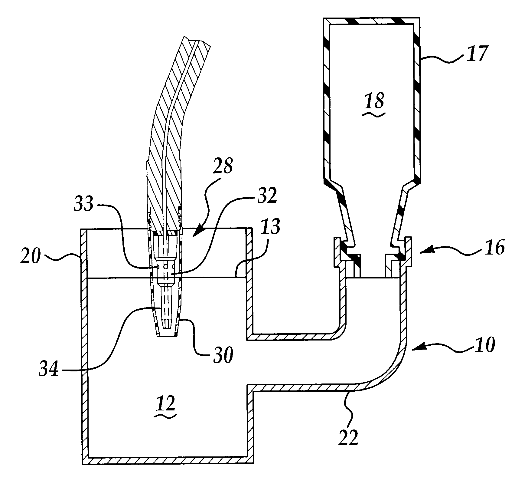
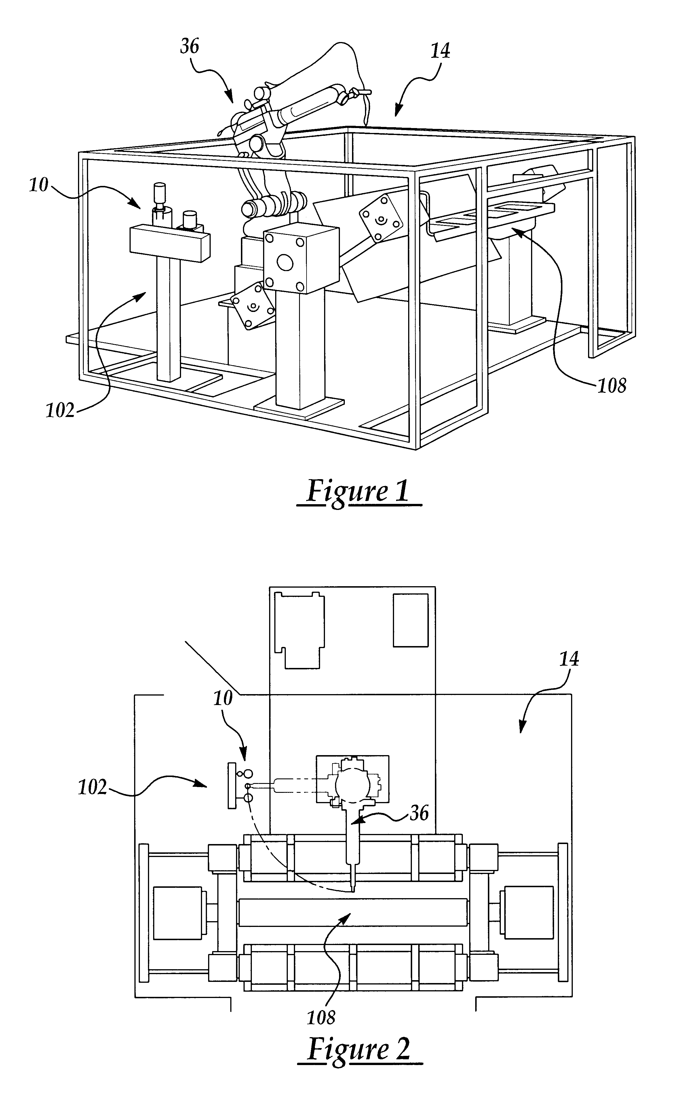
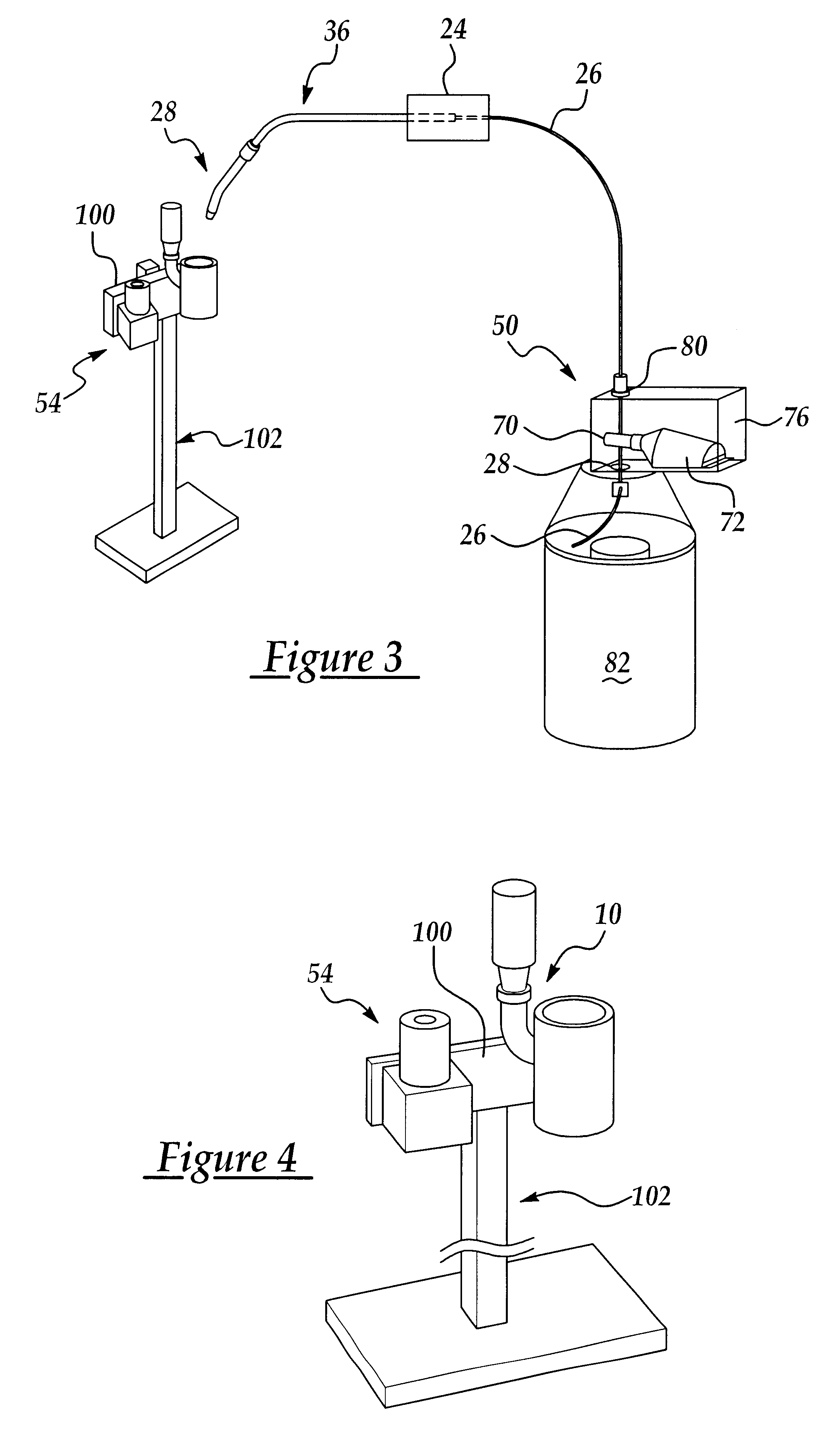
Referring to the Figures, wherein like numerals indicate like or corresponding parts throughout the several views, with particular reference to FIG. 5, an apparatus 10 for providing a bath 12 of a fluid to an automated welding system 14 is shown at 10. The apparatus 10 includes a port 16 for the adaptation of a feed container 17 of fluid 18, a reservoir 20 which is accessible to atmosphere, and a passageway 22 for communication between said feed container 18 and said reservoir 20. The port 16 is preferably comprised of a connection between a threaded spout 5 to the feed container 17 containing the fluid 18 and a mated threaded et 19 to the passageway 22. The apparatus 10 further provides means for maintaining the fluid bath 12 at a constant level within the reservoir 20 until the feed container 18 is exhausted. The relationship between the reservoir 20 and the feed container 18 is such that the apparatus 10 provides a balance between the surface tension of the fluid within the reser...


PUM

PropertyMeasurementUnit
surface tensionaaaaaaaaaa
frictionaaaaaaaaaa
temperatureaaaaaaaaaa

Abstract

Various methods, systems and products are disclosed for providing an improved welding system which substantially improves the continuous operation of an automated welding system by increasing the amount of time between maintenance shutdowns. One of the disclosed method steps or system elements provides for dipping a welding nozzle [28 or 28a] and a portion of its related diffuser into a bath [12 or 12a] of fluid each time the automated welding system moves through a welding cycle. A product is also disclosed to best accomplish that step or element. Another method step or system element may include the removal of spatter accumulation via an electromagnetic field that magnetically pulls the spatter without direct contact with the nozzle or diffuser. A further disclosed method step or system element may include lubrication of the continuous electrode used for welding, and may also include a step or element prior to lubrication that involves cleaning the continuous electrode prior to adding lubricant. The steps or elements may vary as to whether or not they are included, or in what sequence. In each combination of method steps or system elements disclosed, however, a significant increase in time of continuous operation between maintenance shutdowns has occurred. A product is also disclosed that will hold various products as needed for the implementation of each disclosed system or method.

Description

1. Field of the InventionThe subject invention relates to systems and / or methods of use for significantly increasing the amount of time between maintenance shutdowns in an automatic continuous welding application for an automated welding machine. Also disclosed are products which can be used to accomplish some of the steps of the processes or systems disclosed.2. Description of the Prior ArtIn the industry, various welding systems and processes are employed to weld two pieces of metallic material. Typically, a diffuision nozzle (or nozzles in the case of twin electrodes) of a continuous electrode is moved near an article or articles to be welded, and an arc is established between the continuous electrode and the article or articles to be welded, so as to raise the temperature of the article or articles to be welded to the point at which the parts locally melt. Throughout the welding process an inert gas is dispensed through a gas diffuser disposed adjacent the nozzle to keep the mol...

Claims


Application Information

Patent Timeline
Patent Type & Authority Patents(United States)
IPC IPC(8): B23K9/32B23K9/16B08B3/04B08B7/00B23K9/173
CPCB08B3/04B08B7/00B23K9/328B23K9/325B23K9/173
Inventor BAUM, GARY LEEZACCAGNI, ANTHONY JOHN
Owner WELD AID PRODS
Why Eureka
Try Eureka