
Image forming apparatus and image forming method using an extrusion opening and shutter for releasing recording solution

a technology of extrusion opening and recording solution, which is applied in the direction of inking apparatus, printing, duplicating/marking methods, etc., can solve the problems of requiring a large amount of energy for flying the recording solution of high viscosity, the paper sheet itself is creased, etc., and achieves low energy consumption, high quality, and high accuracy.

Inactive Publication Date: 2002-04-23
FUJIFILM BUSINESS INNOVATION CORP
View PDF5 Cites 38 Cited by
  • Summary
  • Abstract
  • Description
  • Claims
  • Application Information

AI Technical Summary

Benefits of technology

The present invention has been achieved in view of the foregoing situations and it is an object thereof to provide an image forming apparatus and an image forming method capable of using a recording solution of a viscosity within a wide range, capable of forming a recording dot at high accuracy with a low energy and capable of obtaining high quality images of recording dots with reduced blot at high speed.
In the present invention, recording is conducted by extruding a recording solution from an extrusion opening and depositing the solution on an image support. A shutter is disposed to the extrusion opening and the extrusion opening is opened only upon recording a dot. Further, after extrusion of the recording solution, the shutter is closed to stop the extrusion of the recording solution. Control for the extrusion amount of the recording solution is enabled by the provision of the shutter to the extrusion opening and drying up of the recording solution can be prevented by closing the extrusion opening with the shutter in a period of time not requiring discharge of the recording solution during printing or in a period of time in which the image forming apparatus is caused to stand-by. In the present invention, since the recording solution is not caused to fly but extrude and flow out continuously, the energy required for recording can be reduced even for a recording solution of high viscosity compared with a case of flying recording droplets. Therefore, it is possible to extend the range for the usable viscosity of the recording solution and form images with a low energy. Particularly, since the recording solution of high viscosity can be used, blot of the recording dot can be prevented, thereby capable of preventing feathering or bleeding.
Further, in a case of using a recording solution of high viscosity, the recording solution extruded out of the extrusion opening is continuous. Therefore, if the image support, for example, is relatively moved as it is, the recording solution causes stringing to form a long tail to the dot recorded on the image support. In the present invention, however, since the stringing of the recording solution can be discontinued by closing the shutter, degradation of the image quality caused by stringing can be prevented.

Problems solved by technology

However, this involves the following basic problems.
Further, when recording is applied by using recording solutions of different colors, color mixing occurs to result in bleeding upon contact of dots adjacent to each other.
However, the blot preventing is still insufficient even in this method, as well as the pre-depositing solution used for the insolubilization of the recording solution is hit previously, so that secondary trouble is caused that the paper sheet itself is creased due to the pre-depositing solution.
The foregoing is problems resulting, particularly, in a case of using a recording solution of low viscosity.
However, in the ink jet system of flying the recording solution by the pressure of air bubbles due to the deformation of a piezoelectric transducer or heating of the recording solution as described above, it was impossible to fly the recording solution of high viscosity or it required a great amount of energy for flying the droplets.
However, the viscosity of the recording solution usable for this system is limited to about 10 mPa.multidot.s.
Further, there is also a problem of requiring heat energy for always heating the recording solution.
In addition, since the volume of the adjacent individual ink channels is also changed by the displacement of the partition walls, the amount of the recording solution is changed due to the change of the volume or the hitting position of the droplet is scattered to possibly deteriorate the quality of recorded images.
Further, since the recording head 51 is in direct contact with the image support 54, there is a problem that the ink deposited on the image support 54 is frictionally rubbed by the top end of the discharge port.
In such a case, even if an ink of high viscosity is used, the image quality cannot be improved.
Further, since only the ink having an electric viscosity can be used, the material of the ink is limited to an extremely narrow range.
Furthermore, since the flow of the ink is controlled by an electric viscosity effect, it involves a fundamental problem that the discharged amount of the ink cannot be controlled if a power source for the apparatus main body is discontinued to possibly leak the ink from the discharge port.

Method used


Image

  • Image forming apparatus and image forming method using an extrusion opening and shutter for releasing recording solution
  • Image forming apparatus and image forming method using an extrusion opening and shutter for releasing recording solution
  • Image forming apparatus and image forming method using an extrusion opening and shutter for releasing recording solution

Examples


example

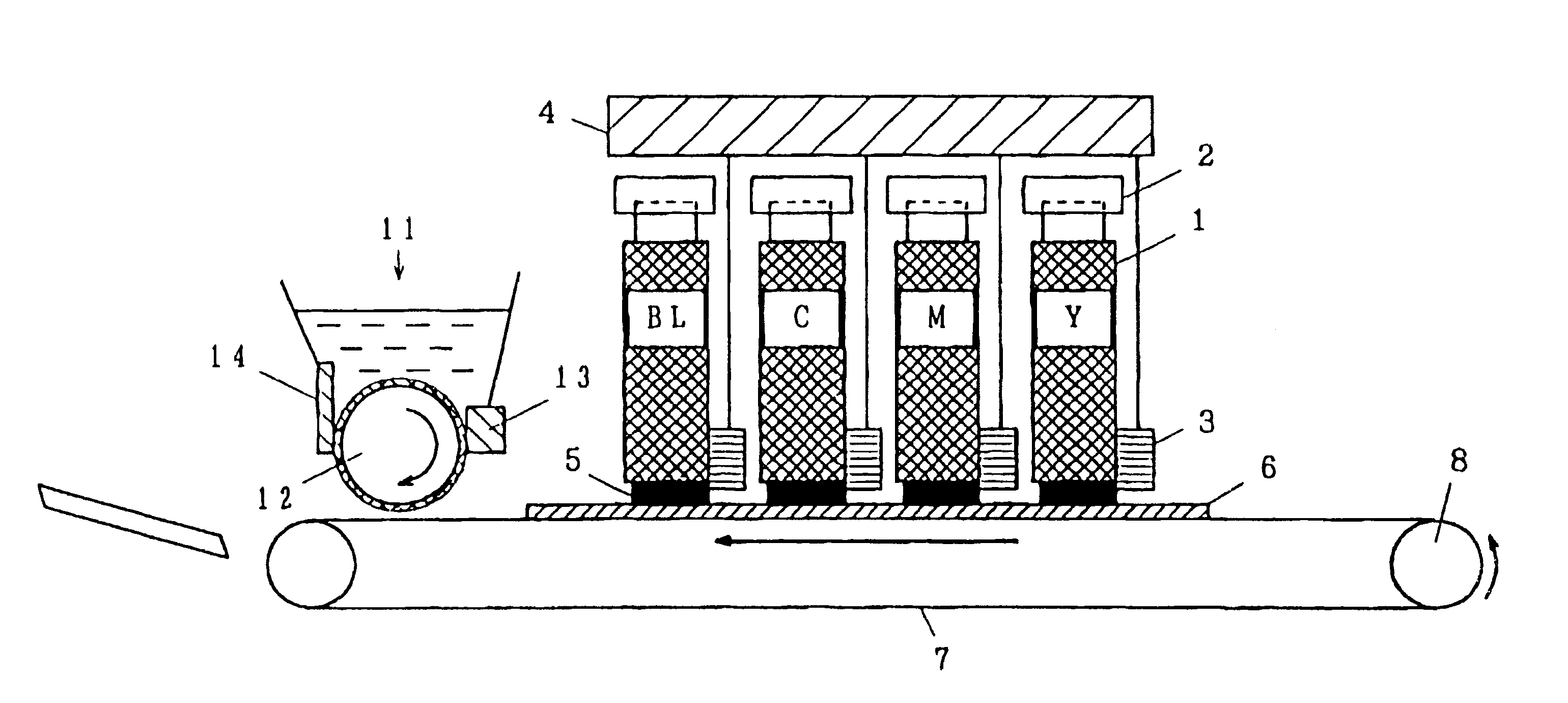
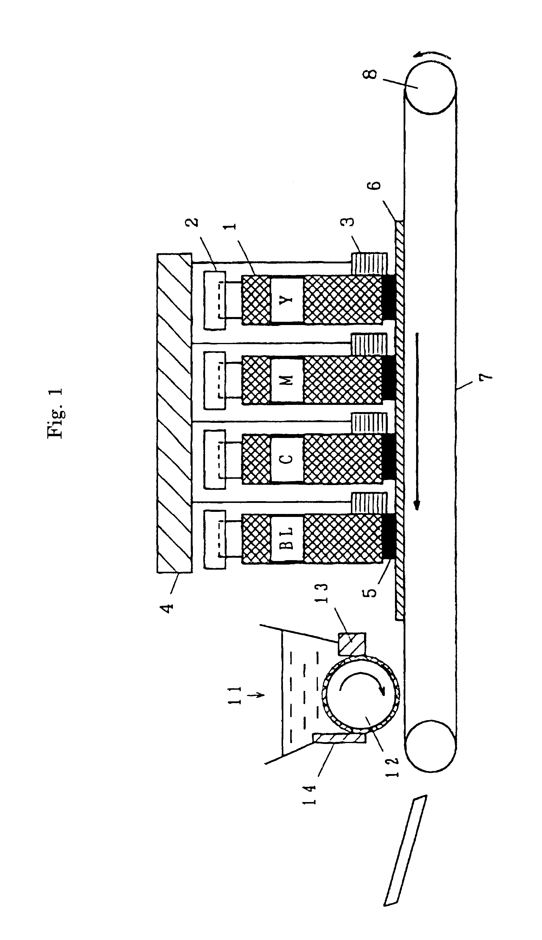
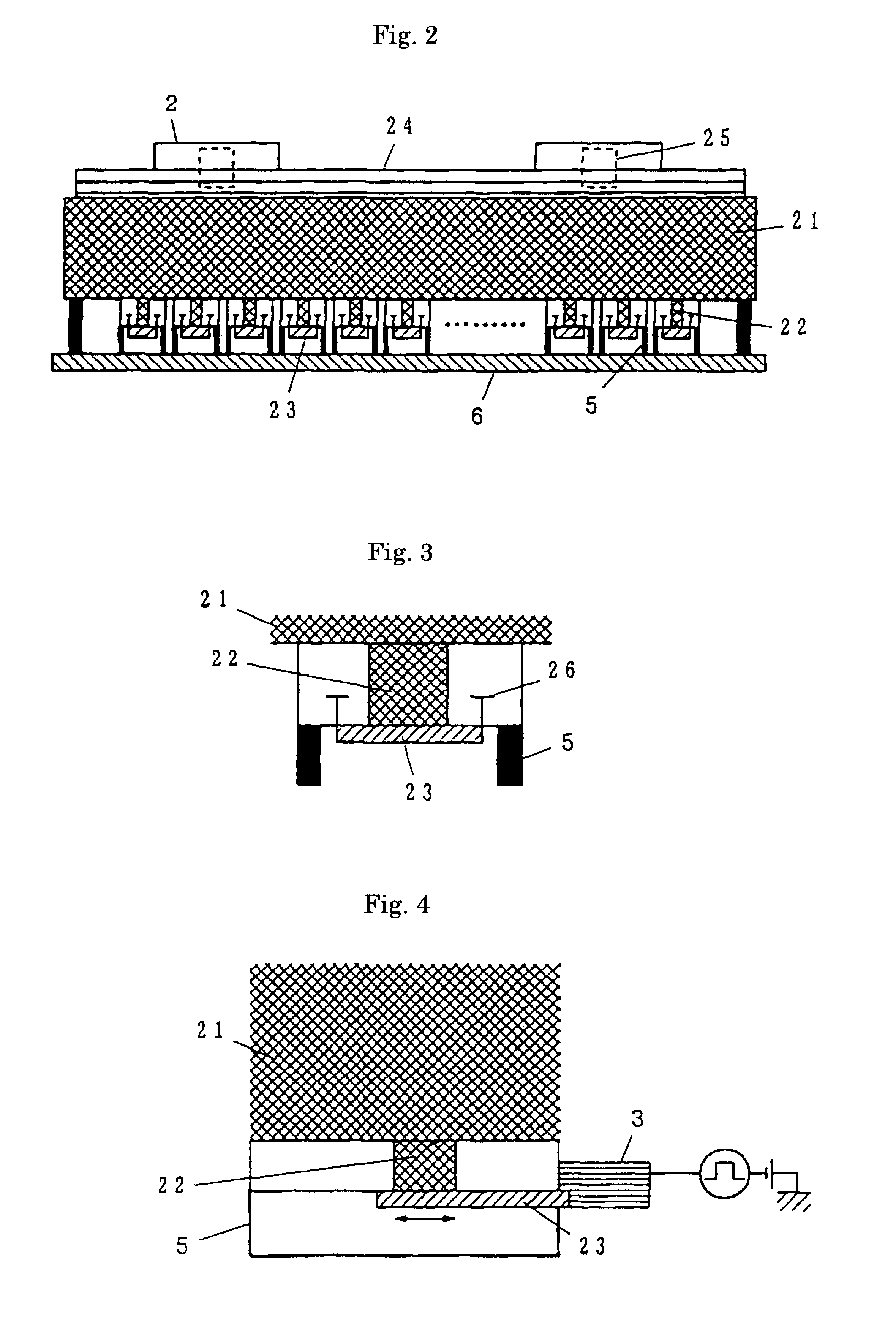
For confirming the printability of the image forming apparatus according to the present invention described above, a print test was conducted. The apparatus used had a constitution shown in FIG. 1 to FIG. 4 in which the materials for the recording head 1 are made of an urethane resin for the recording solution chamber 21 and stainless steel for the portion forming the extrusion opening 2. The length of the extrusion opening 2 in the direction of arrangement was 212 mm. The diameter for the extrusion opening 2 was 70.5 .mu.m. A lamination type piezoelectric element (type 90A, manufactured by Sumitomo Metal Industries, Ltd.) was used as the shutter driving section 3 and the shutter driving speed was set to 200 mm / sec. The feeding speed of the image support 6 was set to 150 mm / sec.

In this example, images were fixed by using a solidifying solution, and 1.5 wt % of special black Bayer-A-SF was used as a black recording solution in which 5 wt % of sodium alginate was dispersed. An aqueous...


PUM

PropertyMeasurementUnit
speedaaaaaaaaaa
viscosityaaaaaaaaaa
viscosityaaaaaaaaaa

Abstract

The recording solution in a recording solution chamber is always pressurized. The shutter is closed when recording is not conducted to prevent the recording solution from flowing out and drying up. The shutter is opened by the shutter driving section in accordance with the image information during recording to open the extrusion opening. The recording solution is extruded from the extrusion opening by the pressurizing force. After the top end of the extruded recording solution is deposited to the opposed image support, the shutter driving section closes the shutter. This discontinues the recording solution flown so far continuously from the extrusion of opening to form a not-stringing recording droplet on the image support. Recording solutions having viscosity in a wide range can be used. The recording dots can be formed accurately with low energy, and high quality images with reduced blot of recording dots can be obtained at high speed.

Description

1. Field of the InventionThe present invention concerns an image forming apparatus for forming images by depositing a recording solution to an image support and an image forming method.2. Related ArtVarious proposals have been made so far for an image forming apparatus of a so-called ink jet system of applying an energy to a recording solution thereby forming and flying minute liquid droplets and depositing the droplets on an image support. The image forming apparatus of the ink jet system includes a scanning type using one or a plurality of nozzles on every color and scanning an image support to conduct recording or an array type using a plurality of nozzles arranged as an array. A mechanism of flying a recording solution used in the ink jet system is, for example, adapted to exert an external force such as pulse pressure on a recording solution in a cavity thereby jetting out particles of the recording solution from a nozzle. The pulse pressure is formed by pressure of air bubbles...

Claims


Application Information

Patent Timeline
Patent Type & Authority Patents(United States)
IPC IPC(8): B41J2/045B41J2/005B41J2/015B41J2/01B41J2/205B41M5/00C08L5/00
CPCB41J2/005B41J2202/05
Inventor KURAMOTO, SHINICHI
Owner FUJIFILM BUSINESS INNOVATION CORP
Learn More