Combined hydrophobic-hydrophilic filter for fluids

a technology of hydrophobic hydrophilic filter and fluid, which is applied in the field of filters, can solve the problems of preventing liquid from being filtered, limiting air passage, and unable to meet the requirements of the flow rate of water,

Inactive Publication Date: 2002-04-23
BEPLATE DOUGLAS K
View PDF3 Cites 32 Cited by
  • Summary
  • Abstract
  • Description
  • Claims
  • Application Information

AI Technical Summary

Problems solved by technology

None of the preceding patents, however, applies to a device which filters the fluid first through the hydrophobic filter and then through the hydrophilic filter or vice-versa.
. . " These filters, furthermore, preclude liquid from reaching a suction pump used to aspirate liquid from a patient.
But even where the pressure differential does exceed the bubble point, the hydrophilic filter when saturated will nevertheless substantially restrict the passage of air."
Moreover, none of the filter material in the preceding patents combines hydrophilic and hydrophobic characteristics on the molecular level.

Method used


Image

  • Combined hydrophobic-hydrophilic filter for fluids
  • Combined hydrophobic-hydrophilic filter for fluids
  • Combined hydrophobic-hydrophilic filter for fluids

Examples


Embodiment Construction

Heat and Moisture Exchange Media (HME), which is commercially available from 3M Filtration Products of St. Paul, Minn., was used for the hydrophilic filter; and Filtrete Air Filter Media Type S, which is, also, commercially available from 3M Filtration Products of St. Paul, Minn., was utilized for the hydrophobic filter.

Five filters were tested. The differential pressure across each filter, utilizing an air flow of 8 liters per minute, was 14.5 mm H.sub.2 O for Filter no. 1, 15.2 mm H.sub.2 O for Filter no. 2, 17.5 mm H.sub.2 O for Filter no. 3, 14.7 mm H.sub.2 O for Filter no. 4, and 15.5 mm H.sub.2 O for Filter no. 5.

A test procedure was conducted to determine the Bacterial Filtration Efficiency (BFE), a ratio of (a) the difference between the number of colony forming units (CFU) in the challenge delivered to the filter and the number of colony forming units in the sample tested after passage through the filter to (b) the number of colony forming units (CFU) in the challenge deliv...


PUM

PropertyMeasurementUnit
pore sizeaaaaaaaaaa
pore sizeaaaaaaaaaa
pressureaaaaaaaaaa

Abstract

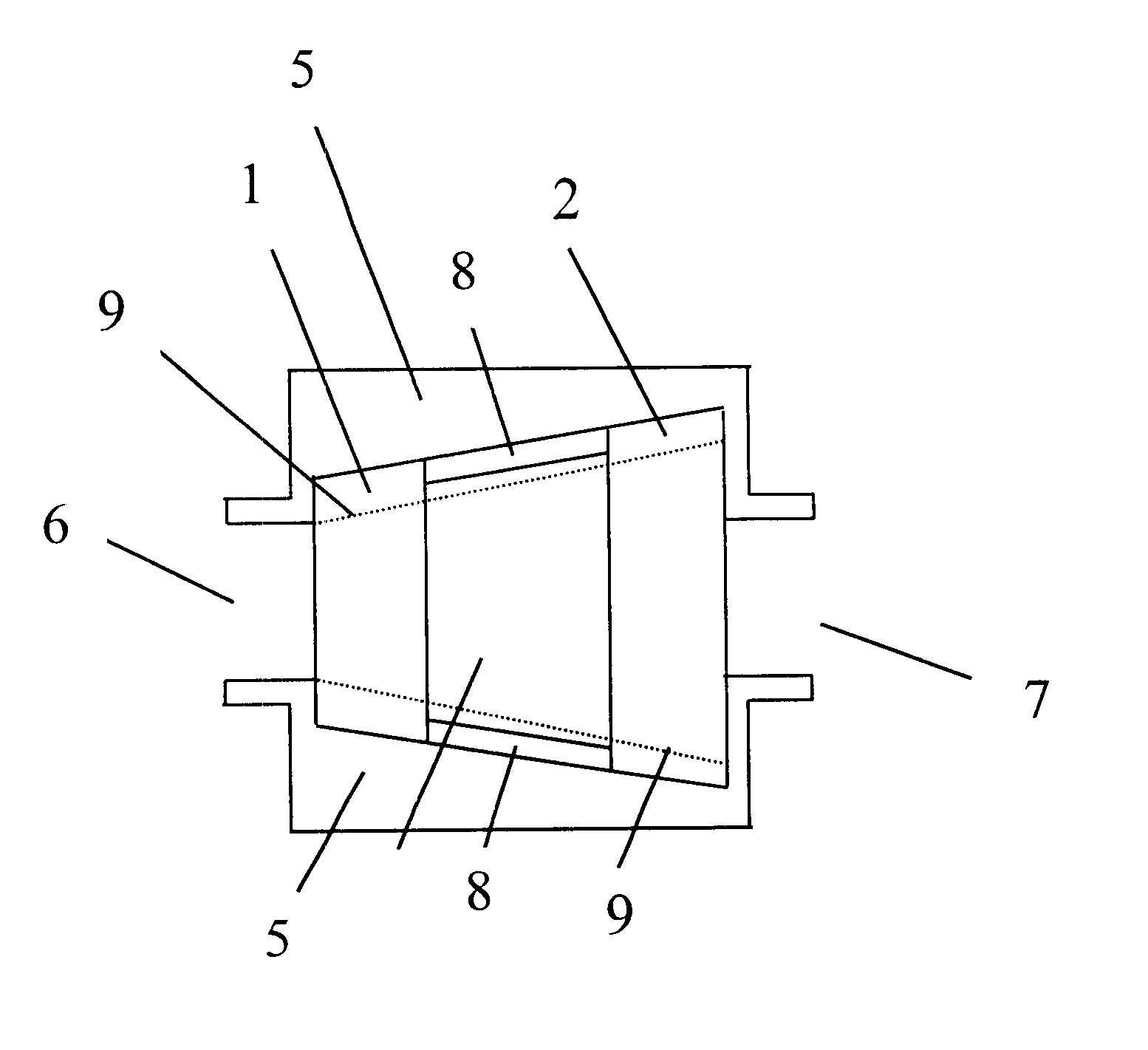
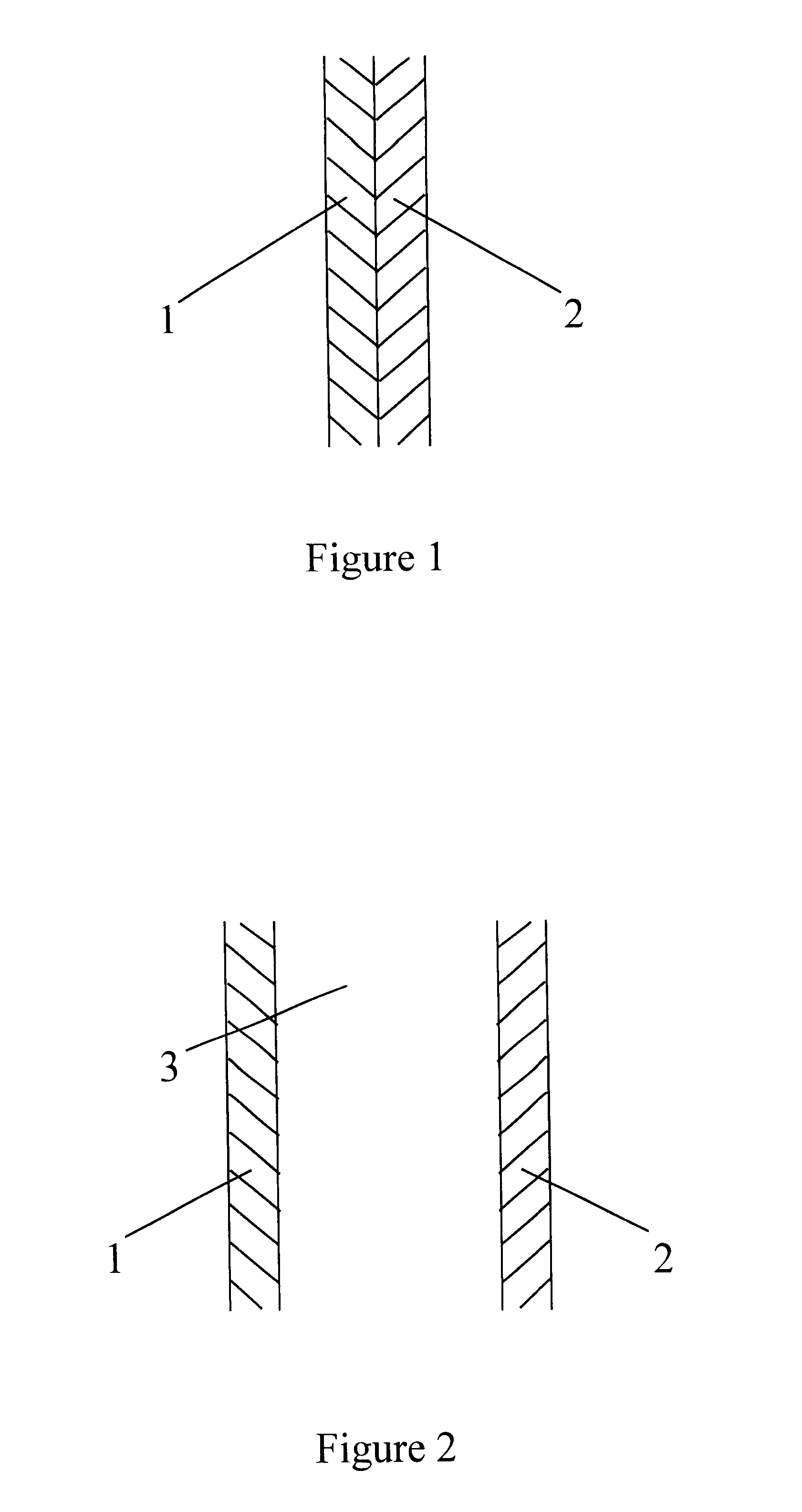
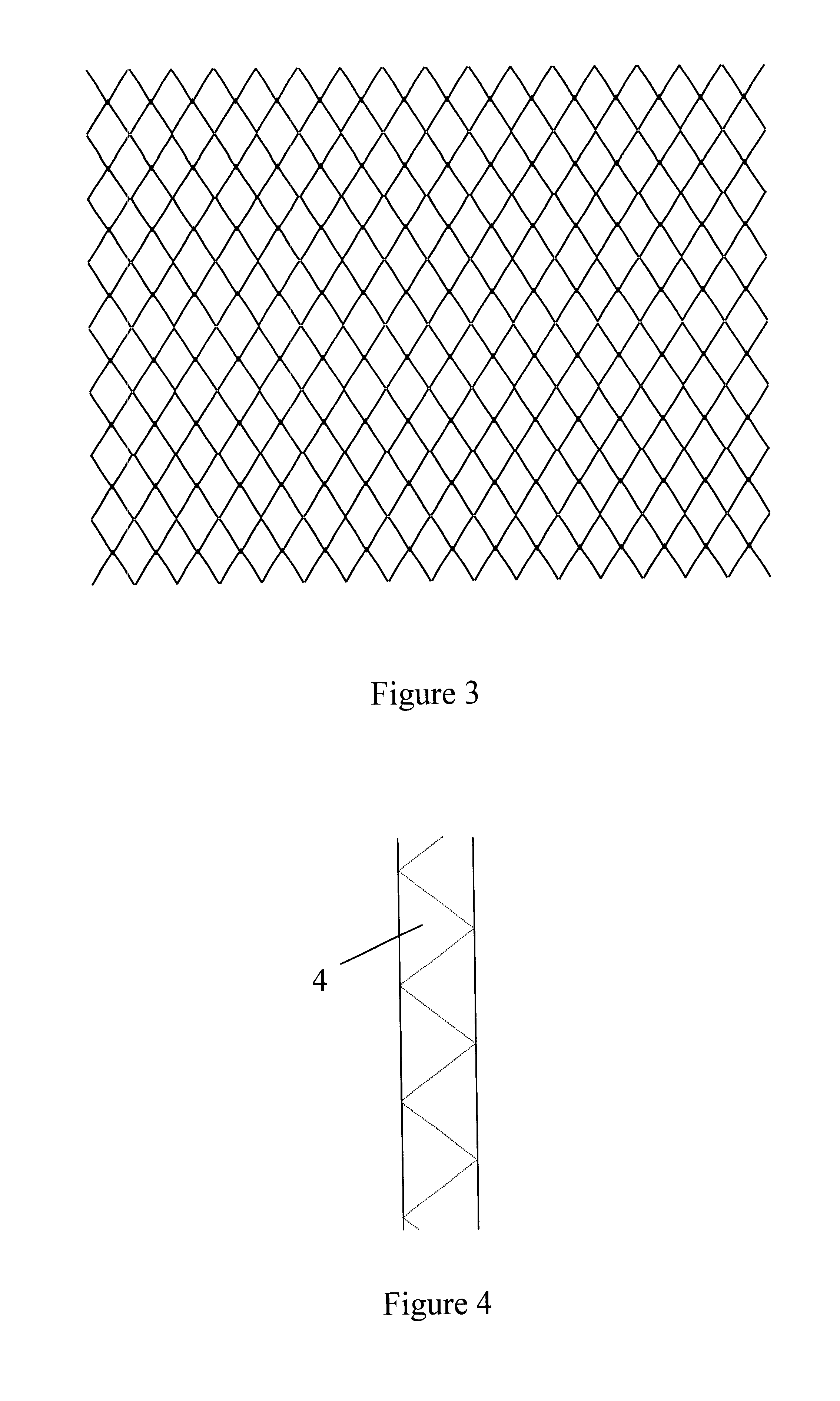
A combined filter for removing an aqueous fluid and entities, such as bacteria, existing in such aqueous fluid, from a nonaqueous fluid is described. The combined filter consists of a hydrophilic filter and a hydrophobic filter that are arranged in fluid communication and serially to be placed along the flow path of a fluid. The hydrophilic filter and the hydrophobic filter may touch one another or be located some distance from one another. Also, a structure may be inserted into the space between the hydrophilic filter and the hydrophobic filter that will maintain the space between the hydrophilic filter and the hydrophobic filter without significantly restricting the flow of fluid. And, in one embodiment, the combined filter may be composed simply of material having both hydrophilic and hydrophobic characteristics on the molecular level. Preferably, however, the filters and spacing structure are contained within an encasement having an inlet and an outlet. As any filter or spacer is located farther downstream with respect to the intended flow of fluid, the dimensions of that filter or spacer in the direction perpendicular to the intended flow of fluid increase to a sufficient extent that, as the stream of fluid expands perpendicularly to its intended direction of flow, the possibility of the fluid contacting any solid element other than a filter is decreased.

Description

1. Field of the InventionThis invention relates to a filter for removing an aqueous fluid and entities, such as bacteria, existing in such aqueous fluid, from a nonaqueous fluid.2. Description of the Related ArtA number of patents are directed toward the combination of a hydrophobic filter and a hydrophilic filter for removing air or other gas from an intravenous fluid before such intravenous fluid reaches a patient. See, e.g., U.S. Pat. Nos. 4,013,072; 4,031,891; 4,116,646; 4,262,668; 4,278,084; 4,515,606; 4,525,182; 4,571,244; 4,615,694; 5,126,054; 5,308,333; 5,439,587; and 5,536,413.None of the preceding patents, however, applies to a device which filters the fluid first through the hydrophobic filter and then through the hydrophilic filter or vice-versa. In each case, the intravenous liquid comes into contact with a hydrophobic filter through which gas from the liquid may escape and then the intravenous liquid passes through a hydrophilic filter.Three patents do, though, apply t...

Claims


Application Information

Patent Timeline
Patent Type & Authority Patents(United States)
IPC IPC(8): A61M5/165B01D69/12B01D61/18B01D69/00B01D61/14B01D19/00C02F1/44B01D71/00
CPCA61M5/165B01D17/08B01D19/0031B01D61/142B01D61/18B01D69/12B01D17/10A61M2205/7518A61M2205/7527A61M2205/7536C02F1/444B01D61/146
Inventor BEPLATE, DOUGLAS K.
Owner BEPLATE DOUGLAS K
Why Eureka
Try Eureka