

Method of vaporizing liquid sources and apparatus therefor
a liquid source and liquid technology, applied in the direction of chemical vapor deposition coating, coating, metallic material coating process, etc., can solve the problems of difficult to maintain a steady flow of source materials, neither suitable for materials, nor suitable for materials whose vapor pressure is very low, and achieve the effect of reducing the possibility of being blocked
- Summary
- Abstract
- Description
- Claims
- Application Information
AI Technical Summary
Benefits of technology
Problems solved by technology
Method used
Image

Examples
embodiment 1
Preferred Embodiment 1
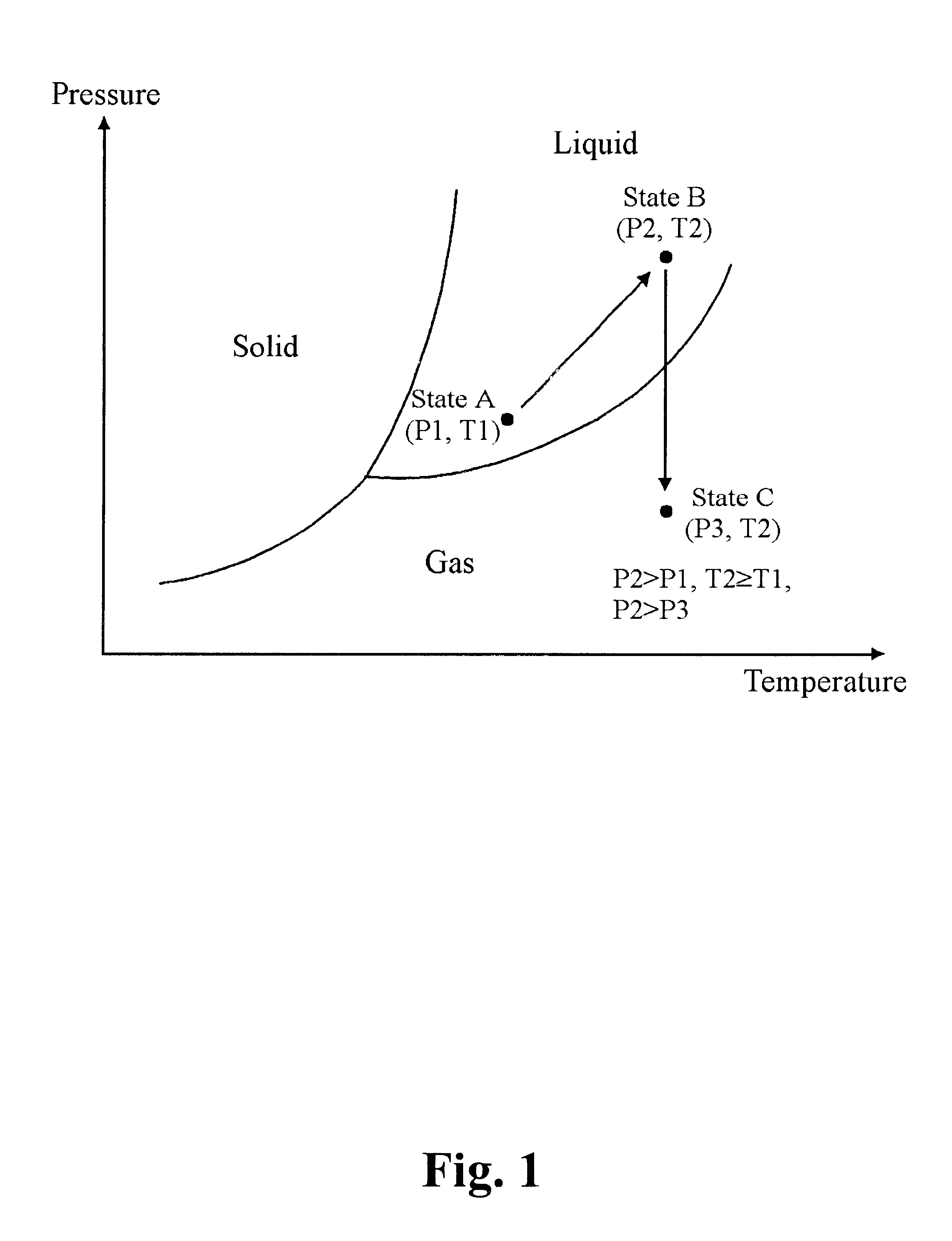
FIG. 1 is a phase diagram showing the boundaries between solid, liquid and gas states for a given liquid source material as a function of temperature and pressure. A liquid copper source material in the equilibrium state of atmospheric pressure (1 atm) and room temperature is pressurized to or above approximately 9 atm, preferably to or above 12 atm, e.g., P2=approximately 12 atm, while the temperature can stay virtually approximately the same, e.g., T1.congruent.T2.congruent.room temperature. The stopper pressure is preferably set at approximately 12 atm. When the pressure of the liquid source material is increased to 12 atm and eventually exceeds the threshold pressure of approximately 12 atm for the stopper, and then the liquid source material pushed the stopper upward, and the vent opens, and as a result, a small gap between the bottom of the stopper and the top of the vent opens. Then, the liquid source material the liquid source material passes through th...
embodiment 2
Preferred Embodiment 2
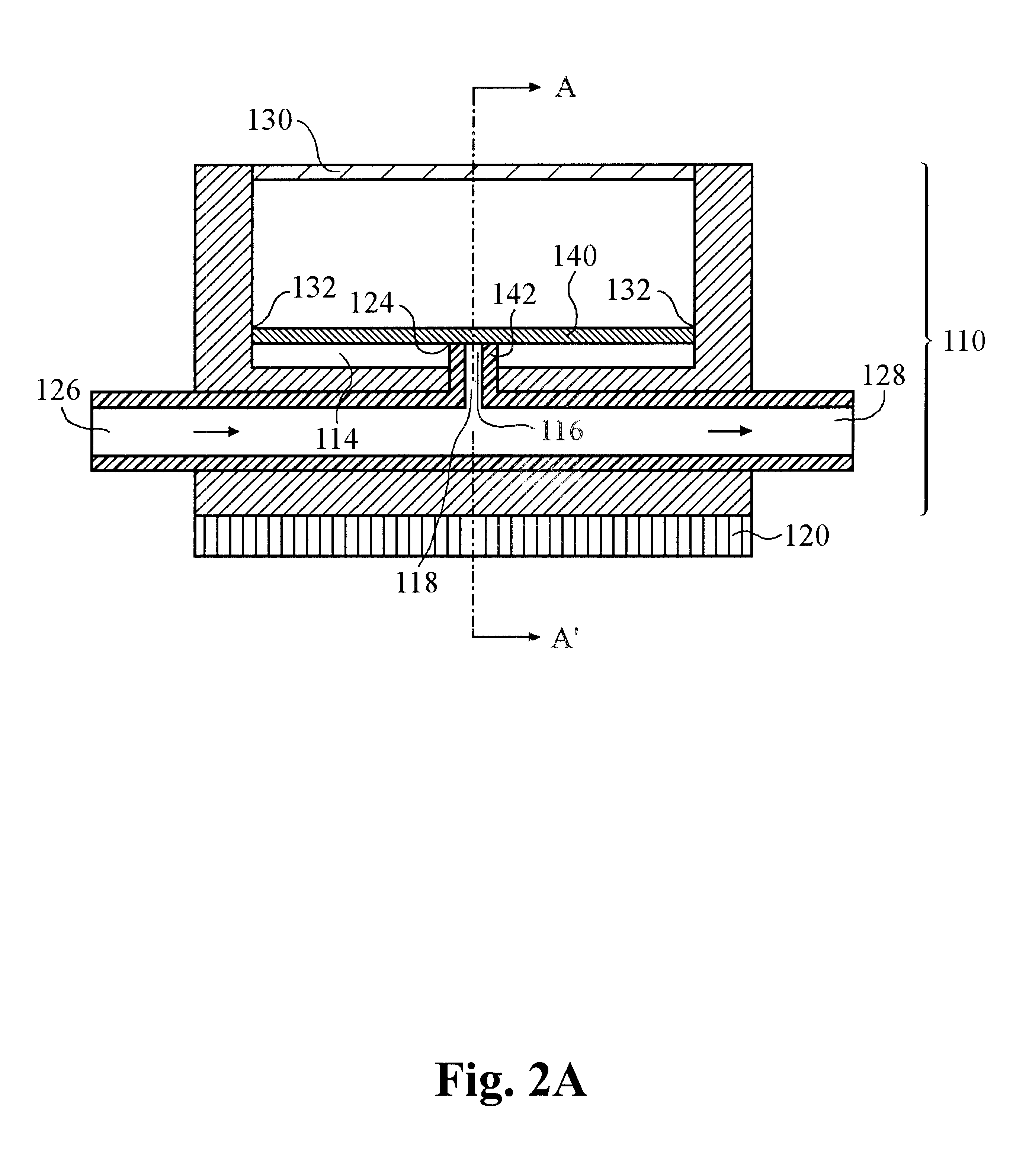
Shown in FIG. 2A is a cross-sectional view of an exemplary apparatus in accordance with one embodiment of the present invention. FIG. 2B is another cross-sectional view of FIG. 2A taken along the line A--A' in FIG. 2A.
The exemplary vaporizing apparatus comprises a main body 110 and an optional heater 120. The main body 110 comprises a liquid source material supply line 112, a reservoir 114, a vent 116, a vent tube 142, a gas discharge tube 118, a stopper 140, a pressurized contact surface 124, an inlet carrier gas tube 126, an outlet carrier gas tube 128 which is connected to the inlet carrier gas tube 126, a pressurizer 130 and, a pressure tight contact 132 between the main body 110 and the stopper 140. The height of the vent tube 142 determines the desired space for the reservoir 114. A conventional metering pump 150 (not shown) is connected to the liquid source material supply line 112.
The optional heater 120 that heats the main body as well as the liquid so...
embodiment 3
Preferred Embodiment 3
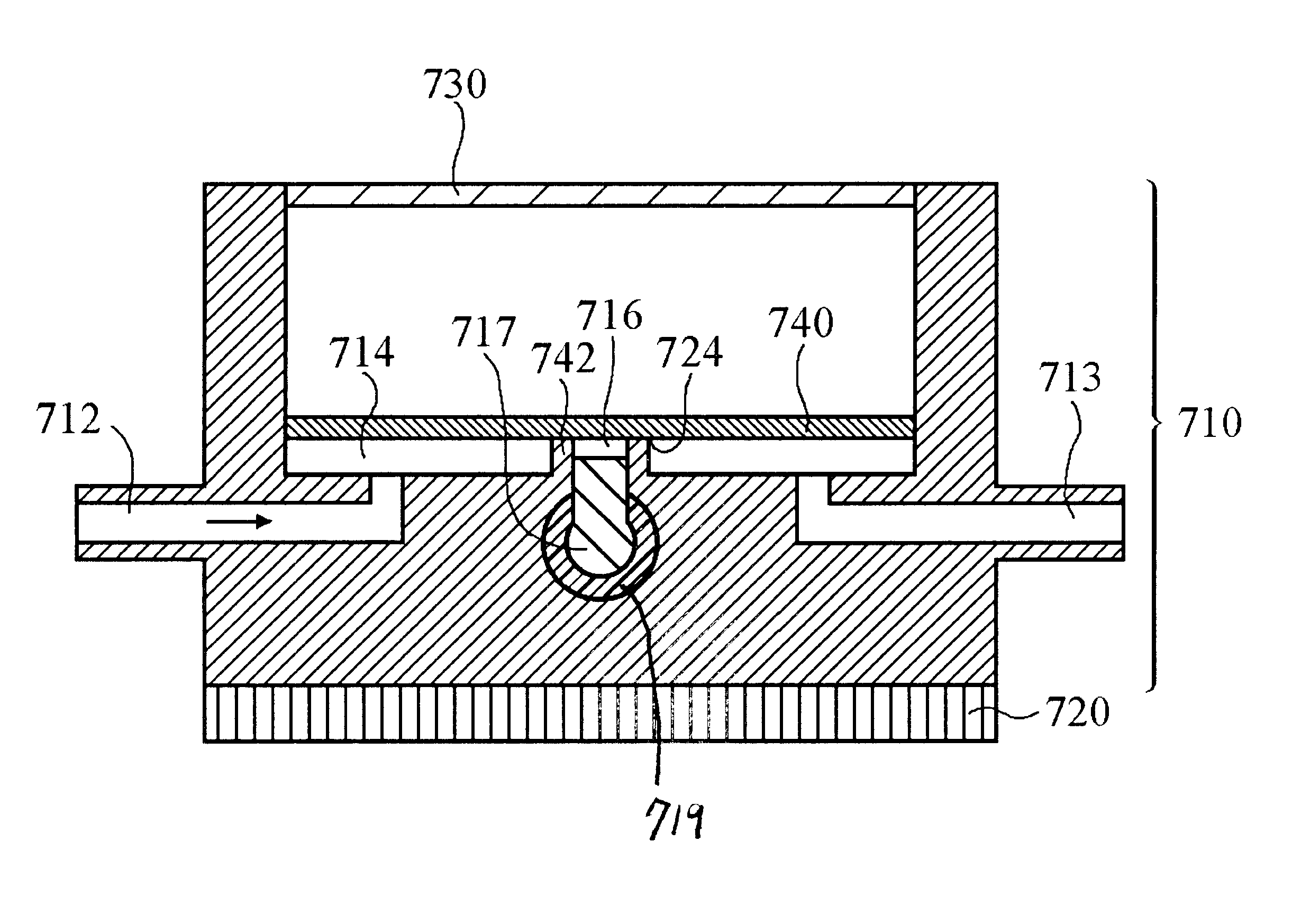
An exemplary apparatus for vaporizing liquid source material with a mechanical pressurizer is disclosed and presented here. Similar features among FIGS. 2A, 2B and 3 are designated similarly but with differentiated hundreds, e.g. 114 and 214 correspond.
Referring to FIG. 3, the proposed apparatus is another aspect of the apparatus disclosed and presented in the Preferred Embodiment 2 above with the exception of vertically connected inlet and outlet carrier gas tubes 226 and 228, where the inlet carrier gas tube 226 and the outlet carrier gas tube 228 are connected with a vent 116 in the middle, where the combination of the inlet carrier gas tube 226 and the outlet carrier gas tube 228 is called the gas transport tube 219. vertically connected liquid source material supply line 212, more significantly, a mechanical stopper 240 and a clean-out tube 213, which is closed during a normal operation.
As the pressure in the reservoir 214 is increased until it exceeds the...
PUM
| Property | Measurement | Unit |
|---|---|---|
| Temperature | aaaaa | aaaaa |
| Pressure | aaaaa | aaaaa |
| Flow rate | aaaaa | aaaaa |
Abstract
Description
Claims
Application Information