Eureka AIR delivers breakthrough ideas for toughest innovation challenges, trusted by R&D personnel around the world.

Process for producing phthalic anhydride

a technology of phthalic anhydride and process, which is applied in the preparation of carboxylic compounds, organic chemistry, chemistry apparatus and processes, etc., can solve the problems of marked deterioration of catalysts, reducing the yield of phthalic anhydride, and affecting the performance of such catalysts

Inactive Publication Date: 2002-04-30
NIPPON SHOKUBAI CO LTD
View PDF12 Cites 19 Cited by
  • Summary
  • Abstract
  • Description
  • Claims
  • Application Information

AI Technical Summary

Problems solved by technology

However, the performances of such catalysts are susceptible to improvement.
However, a reaction of ortho-xylene and / or naphthalene to yield phthalic anhydride is a highly exothermic reaction, and under such high loading conditions, the temperature of a hot spot vigorously increases and an excessive oxidation reaction occurs to markedly deteriorate the catalyst.
As a result, the yield of phthalic anhydride is decreased.
If the temperature of the hot spot excessively increases, heat of reaction cannot be sufficiently removed, which will induce a runaway reaction.
However, even when such catalysts are used, decrease in the yield of phthalic anhydride, deterioration of catalyst and the danger of a runaway reaction cannot be avoided unless excessive temperature rise in a hot spot is controlled.
However, if conversion of a raw material in individual catalytic layers is out of valance, the temperature in a hot spot still excessively vigorously rises to thereby invite an excessive oxidation reaction.
As a result, this configuration cannot also solve the problems of decrease in yield of phthalic anhydride and deterioration of the catalyst.
As a result, the hot spot temperature in the second catalytic layer excessively increases to thereby deteriorate the yield of phthalic anhydride.
In contrast, if the conversion rate at an outlet of the first catalytic layer exceeds 70%, the hot spot temperature in the first catalytic layer extremely increases as excessively large amounts of heat is evolved in the first catalytic layer, and the reaction in the first catalytic layer becomes markedly unstable.
In this case, the hot spot cannot be significantly controlled to invite a runaway reaction.
Even if no runaway reaction occurs, the catalyst is thermally deteriorated in the hot spot, and the yield of phthalic anhydride is further deteriorated with time.
In addition, the reaction cannot be completed in catalytic layers from the third catalytic layer to a final catalytic layer, and the quality of product phthalic anhydride cannot be maintained.
In contrast, a .DELTA.T less than the lower limit of the above range means that the reaction amount in the catalytic layer in question excessively decreases.
Loads on the other catalytic layers therefore increase and the reactions get out of balance to thereby deteriorate the yield of phthalic anhydride.
In severe cases, heat evolution in the other catalytic layers excessively increase, and the conversion rates specified in the invention are hardly obtained.

Method used


Image

  • Process for producing phthalic anhydride
  • Process for producing phthalic anhydride
  • Process for producing phthalic anhydride

Examples


production example 1

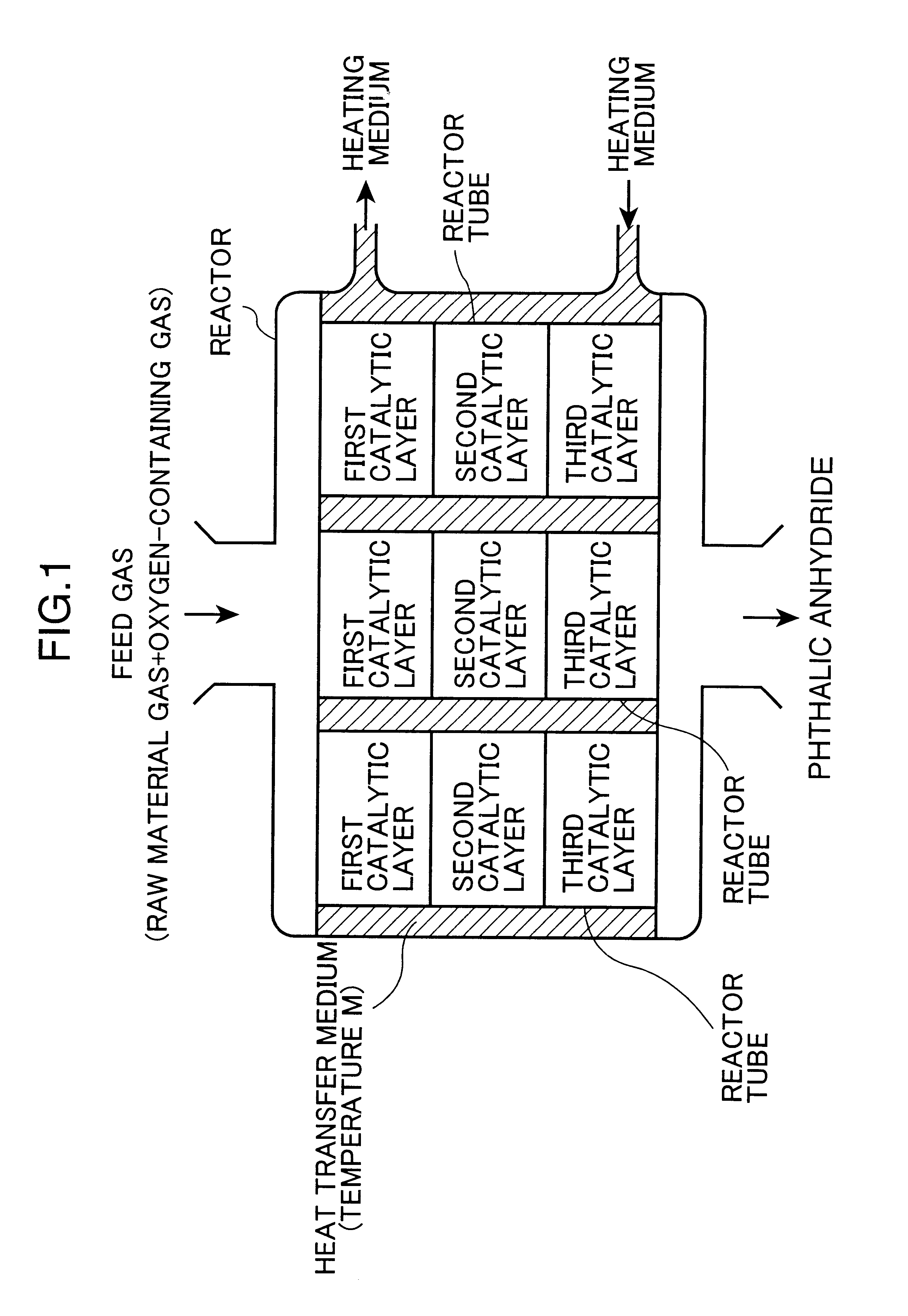
Into an iron tubular reactor 25 mm in internal diameter and 3.5 m in length, Catalyst C as a third catalyst was packed to a height of 0.9 m to form the third catalytic layer, and onto this layer Catalyst B as a second catalyst was packed to a height of 0.9 m to form the second catalytic layer, and Catalyst A as a first catalyst was then packed thereonto to a height of 0.9 m to form the first catalytic layer.

The above-prepared tubular reactor was dipped into a molten salt bath at 350.degree. C., and a mixed gas containing ortho-xylene and air in a ratio of 100 g / Nm.sup.3 (100 gram of ortho-xylene relative to 1 m.sup.3 of air at standard temperature and pressure) was fed into the dipped tubular reactor at a rate of 4.0 Nm.sup.3 / hr (space velocity at standard temperature and pressure: 3000 Hr.sup.-1).

The yield of phthalic anhydride and the amount of phthalide, an intermediate by-product, were determined respectively at an initial stage of the reaction and 3 months after starting the r...

production examples 2 to 4

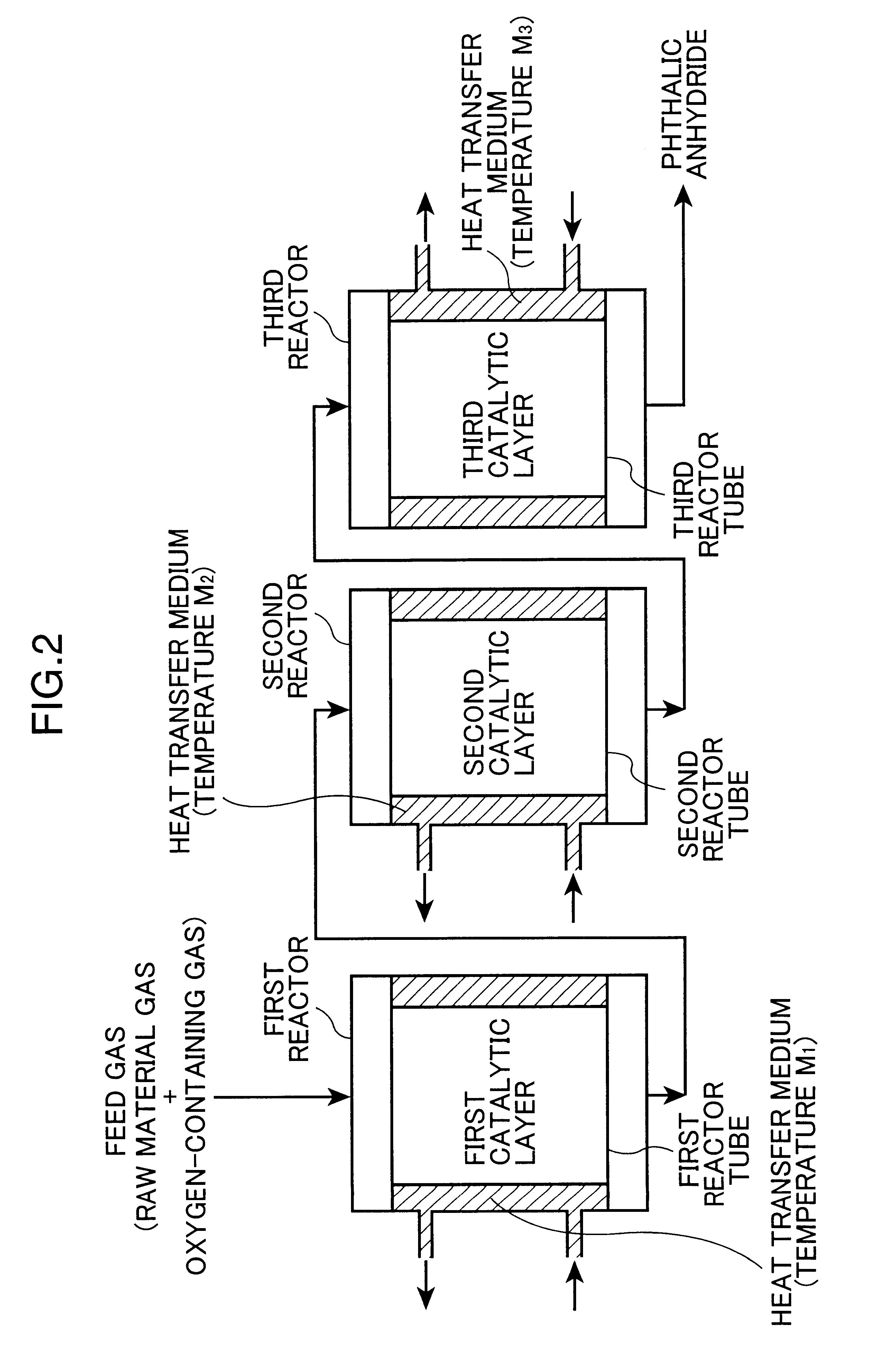
Phthalic anhydride was produced in the same manner as in Production Example 1, except that the first, second, and third catalysts were changed to those indicated in Tables 3 and 4, and that the temperatures (M) of the molten salt baths were changed to those indicated in Tables 3 and 4. The conversion rates of the first and second catalytic layers, and the hot spot temperatures of the first, second, and third catalytic layers were measured respectively at an initial stage of the reaction and 3 months after starting the reaction, according to the measuring methods in continuous catalytic layer type system. In addition, the yield of phthalic anhydride and the amount of phthalide were determined. The results are shown in Table 3 (at an initial stage of the reaction) and Table 4 (3 months later).

production example 5

Each individual catalytic layer was formed from a mixture of Catalyst J and a spherical SiC self-sintered carrier having a diameter of 6mm, an apparent porosity of 35% and a purity of 98.5%. The contents of Catalyst J in the mixtures were set to 35% by weight, 60% by weight, and 100% by weight respectively for the first, second, and third catalytic layers.

Respectively at an initial stage of the reaction and 3 months after starting the reaction, the conversion rates of the first and second catalytic layers, and the hot spot temperatures of the first, second, and third catalytic layers were measured, according to the measuring methods in continuous catalytic layer type system. In addition, the yield of phthalic anhydride and the amount of phthalide were determined. The results are shown in Table 3 (at an initial stage of the reaction) and Table 4 (3 months later).


PUM

PropertyMeasurementUnit
specific surface areaaaaaaaaaaa
porosityaaaaaaaaaa
porosityaaaaaaaaaa

Abstract

The invented process produces phthalic anhydride through gas-phase catalytic oxidation of ortho-xylene and / or naphthalene with an oxygen-containing gas using one or more fixed bed reactors. In the process, the gas-phase catalytic oxidation process is performed in three or more individual catalytic layers, and the conversion rates of ortho-xylene and / or naphthalene in the individual layers are controlled within specific ranges. The process is capable of providing phthalic anhydride in a high yield, is capable of minimizing deterioration of catalysts with time, and is capable of continuously stably producing phthalic anhydride in safety, even when a high concentration material gas is fed.

Description

1. Field of the InventionThe present invention relates to a process for producing phthalic anhydride using a fixed bed reactor. Particularly, the invention relates to a process for producing phthalic anhydride in a high yield by gas-phase catalytic oxidation of ortho-xylene and / or naphthalene with molecular oxygen or an molecular-oxygen-containing gas using a fixed bed reactor.2. Description of the Related ArtPhthalic anhydride is produced by a process of gas-phase catalytic oxidation of ortho-xylene and / or naphthalene with molecular oxygen or a molecular-oxygen-containing gas (these are hereinafter briefly referred to as "oxygen-containing gas"). In this process, the use of catalysts each containing vanadium oxide and titanium oxide as active ingredients supported on an inert carrier is widely known, and is described in, for example, Japanese Examined Patent Application Publications No. 47-15323, No. 49-41036, and No. 52-4538, and Japanese Unexamined Patent Application Publications...

Claims


Application Information

Patent Timeline
Patent Type & Authority Patents(United States)
IPC IPC(8): C07C51/16C07C51/265C07C51/31C07D307/89
CPCC07C51/265C07C51/313C07C63/16C07D307/89
Inventor OKUNO, MASAAKITAKAHASHI, TSUKASA
Owner NIPPON SHOKUBAI CO LTD
Why Eureka
Eureka Blog
Learn More