Variable structure circuit topology for HID lamp electronic ballasts

a technology of variable structure circuit and electronic ballast, which is applied in the direction of electric variable regulation, process and machine control, instruments, etc., can solve the problems of high circulating resonant current, high ignition voltage generation using the resonant method, and q1, q2, in hard switching mode, etc., and achieve high speed

Inactive Publication Date: 2002-04-30
MATSUSHITA ELECTRIC WORKS LTD
View PDF10 Cites 84 Cited by
  • Summary
  • Abstract
  • Description
  • Claims
  • Application Information

AI Technical Summary

Benefits of technology

According to an advantage of the present invention, the switching devices may be MOSFET transistors. Each MOSFET transistor may include an integrated high speed diode.
According to another advantage of the present invention, the driving circuit operates in a half-bridge topology during the lamp-starting mode, and a full-bridge topology during the lamp-running mode.
A feature of the present invention is that two switching devices of the plurality of switching devices and one inductor/capacitor filter of the pair of inductor/capacitor filters operate as a high frequency resonant mode switch to turn ON the lamp. The high frequency resonant mode switch is turned ON for a predetermined period of time after a lamp breakdown to provide a smooth transition from when a glowing condition to an arcing condition.
Another feature of the present invention is that one inductor/capacitor filter of the pair of inductor/capacitor filters comprises a high frequency resonant filter during the lamp starting mode, while a remaining inductor/capacitor filter of the pair of inductor/capacitor filters comprises a high frequency ripple reducing filter during the

Problems solved by technology

Accordingly, generation of a high ignition voltage using the resonant method necessarily suffers from high circulating resonant current in the resonant elements and driving source switches.
The disadvantages of this arrangement become apparent when it is considered that the high frequency attenuation is only -20 dB/decade (logarithmic decade) for frequencies above the corner frequency (the corner frequency being formed by the lamp LMP impedance and the inductance L1).
Another disadvantage of this arrangement is that the switching elements Q1, Q2 are in hard switching mode during the switch turn-on interval.
The necessary switches are expensive because external ultra-fast freewheeling diodes in the order of 20-50 nS reverse recovery time are required.
Moreover, switching losses are relatively high.
A drawback o

Method used


Image

  • Variable structure circuit topology for HID lamp electronic ballasts
  • Variable structure circuit topology for HID lamp electronic ballasts
  • Variable structure circuit topology for HID lamp electronic ballasts

Examples


Embodiment Construction

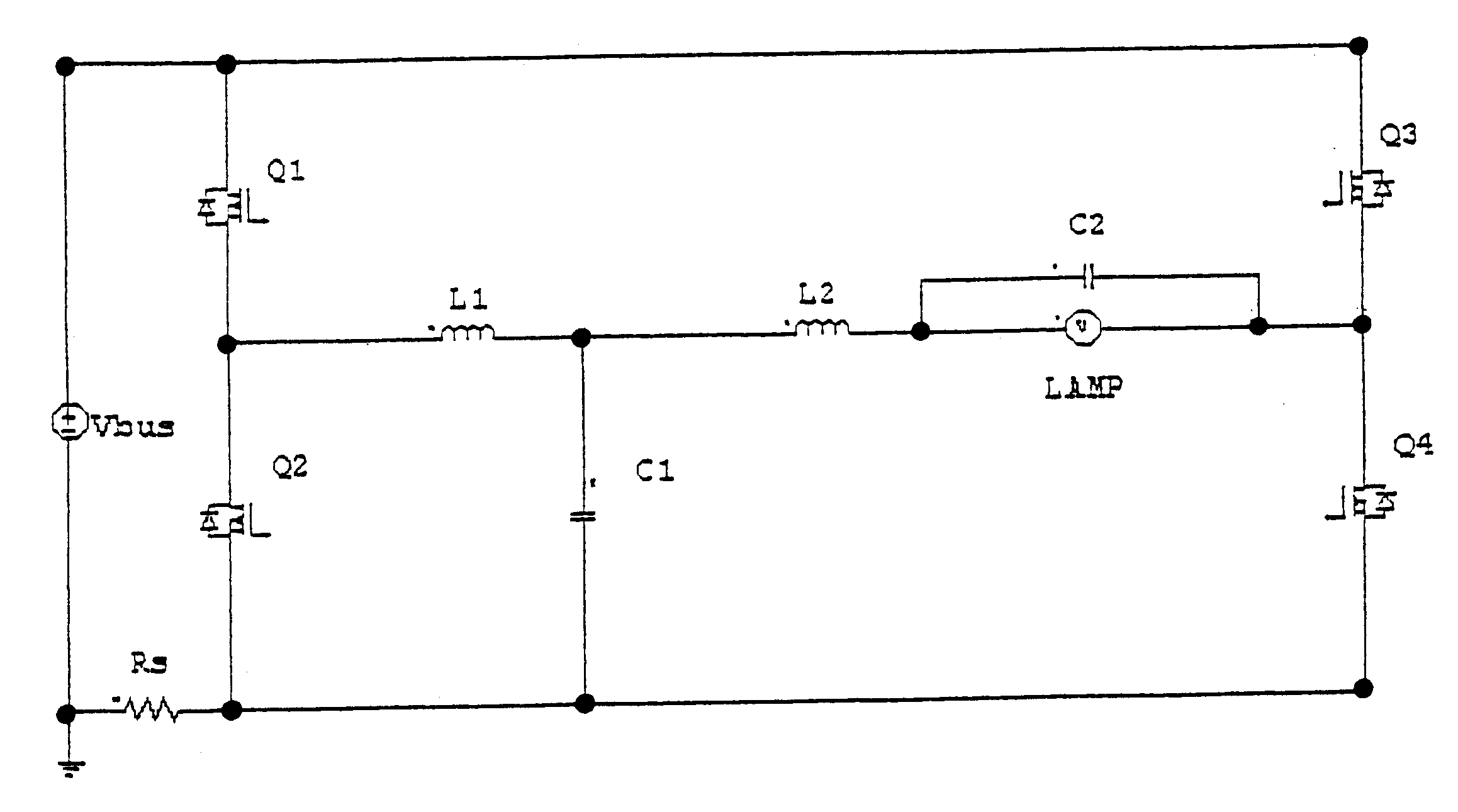
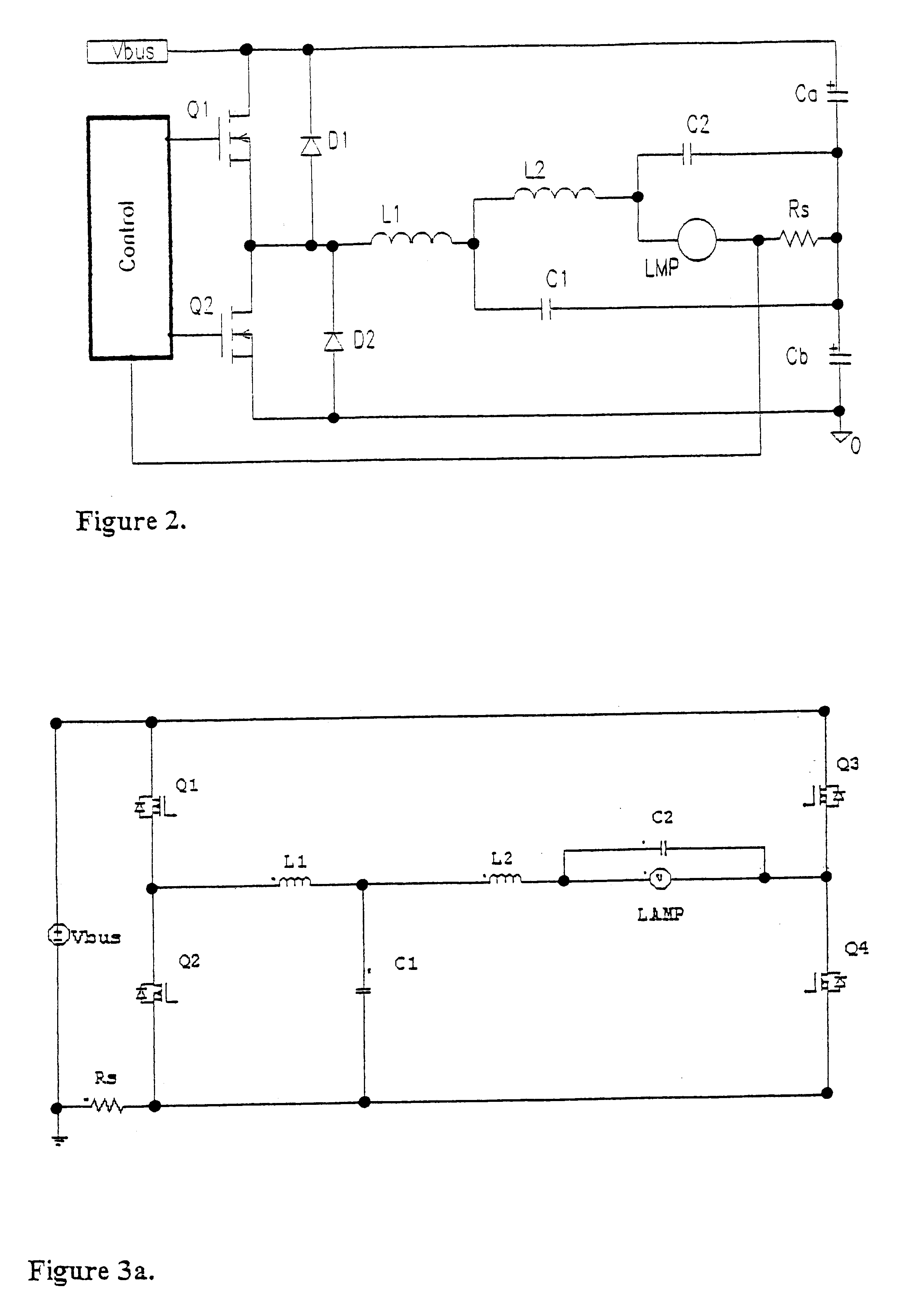
FIG. 3a illustrates one embodiment of the present invention. As shown in FIG. 1, the drive circuit includes a power source Vbus that is operated through a circuit control (not shown). The circuit of FIG. 3a also illustrates four high frequency switching devices Q1, Q2, Q3, and Q4 which are connected to the power source Vbus. In the disclosed embodiment, high frequency switching devices Q1 to Q4 comprise a high frequency semiconductor device, such as, for example, a MOSFET transistor. However, it is understood that alternative semiconductor devices, such as, for example, a bipolar transistor, may be used without departing from the scope and / or spirit of the instant invention. In the illustrated embodiment of FIG. 3a, switching devices Q1 to Q4 are shown as high frequency MOSFET devices. Preferably, each high frequency MOSFET device includes an integrated high speed diode. However, it is understood that the diode may be external to the MOSFET device, without departing from the scope a...


PUM


Abstract

A high intensity discharge (HID) lamp driving circuit. The HID lamp driving circuit includes a first pair of switching devices connected to a high frequency resonant filter, and a second pair of switching devices connected to a ripple reducing filter. A HID lamp is connected between the first pair of switching devices and second pair of switching devices, with a dc power supply being connected to the first pair of switching devices and the second pair of switching devices. The first pair of switching devices and the second pair of switching devices are connected to a common ground with the dc power supply. The lamp driving circuit operates in a half bridge topology during a start-up operation mode of the lamp, and operates in a full-bridge topology during a steady-state operation mode of the lamp. The HID lamp driving circuit is operated in an active zero current switching scheme.

Description

1. Field of the InventionThe present invention relates to a variable structure circuit topology for high intensity discharge (HID) lamp electronic ballasts.2. Description of Background InformationIn electronic high intensity discharge lamp ballasts, there are two distinctly different methods to drive the lamp. The first method is to drive the lamp with high frequency sinusoidal current, and the second is to drive the lamp with low frequency rectangular current. The high frequency sinusoidal current method tends to give rise to acoustic resonance. Accordingly, low frequency rectangular current wave operation remains the favored technique for electronic high intensity discharge lamp ballasts because of the acoustic resonance problem associated with the high frequency method.Two fundamental approaches are generally taken to generate a low frequency (less than 1 kHz) rectangular current with very small high frequency ripple to the lamp, as shown in comparative examples in FIGS. 1a and 1...

Claims


Application Information

Patent Timeline
IPC IPC(8): H05B41/28H05B41/38H05B41/288H05B41/24
CPCH05B41/2883H05B41/382H05B41/2888Y02B20/204Y02B20/00
Inventor UCHIHASHI, KIYOAKINANDAM, PRADEEP KUMAR
Owner MATSUSHITA ELECTRIC WORKS LTD
Why Eureka
Try Eureka