

Component for a gas turbine
- Summary
- Abstract
- Description
- Claims
- Application Information
AI Technical Summary
Benefits of technology
Problems solved by technology
Method used
Image

Examples
second embodiment
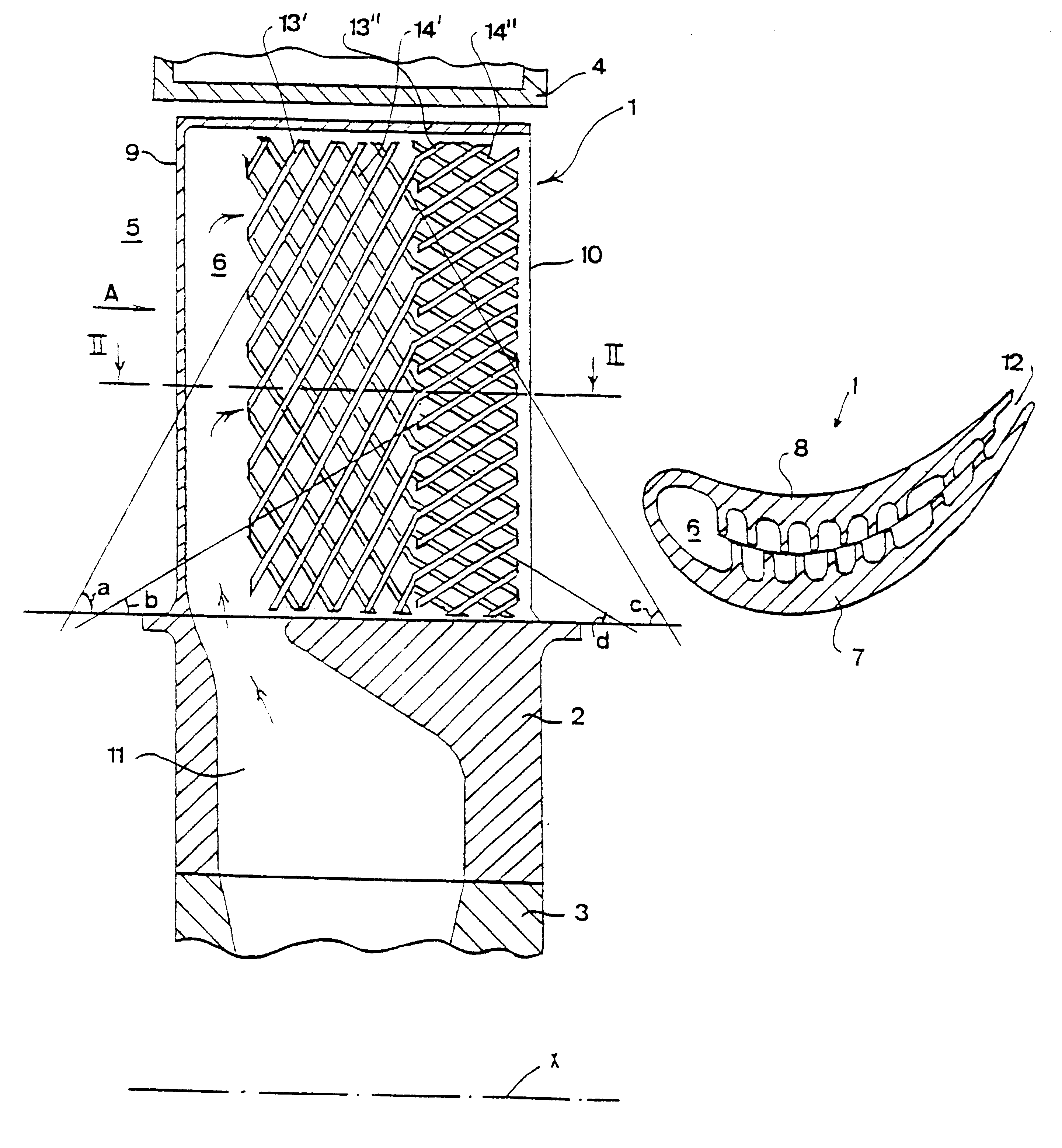
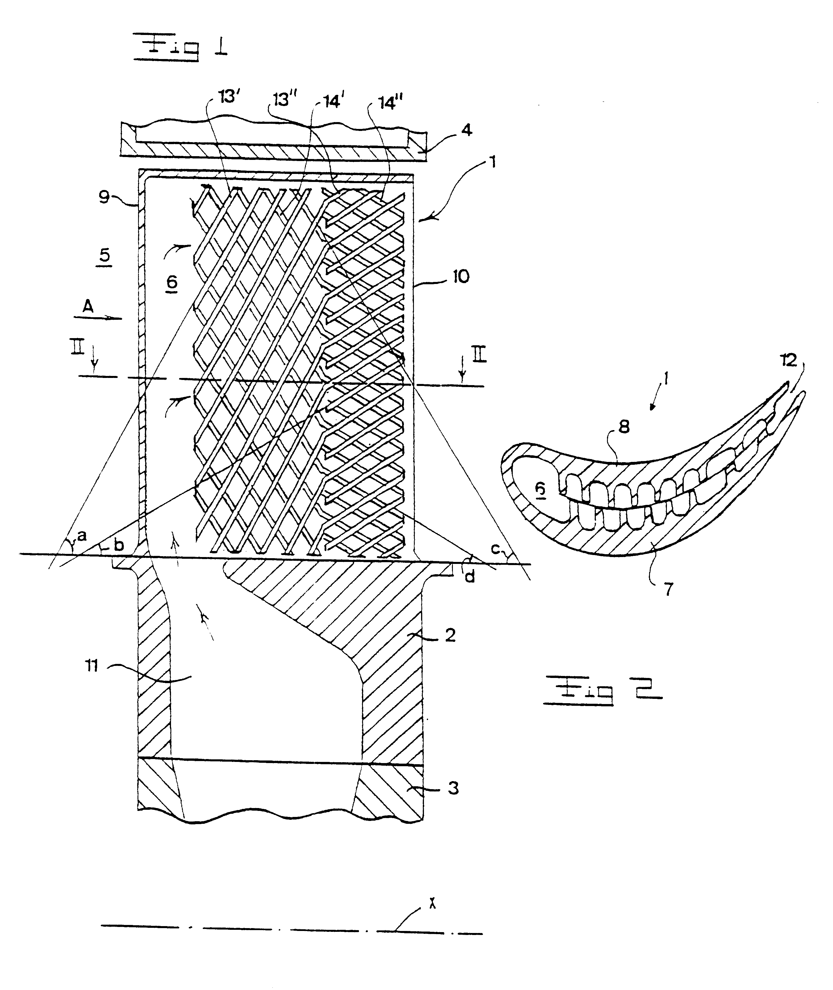
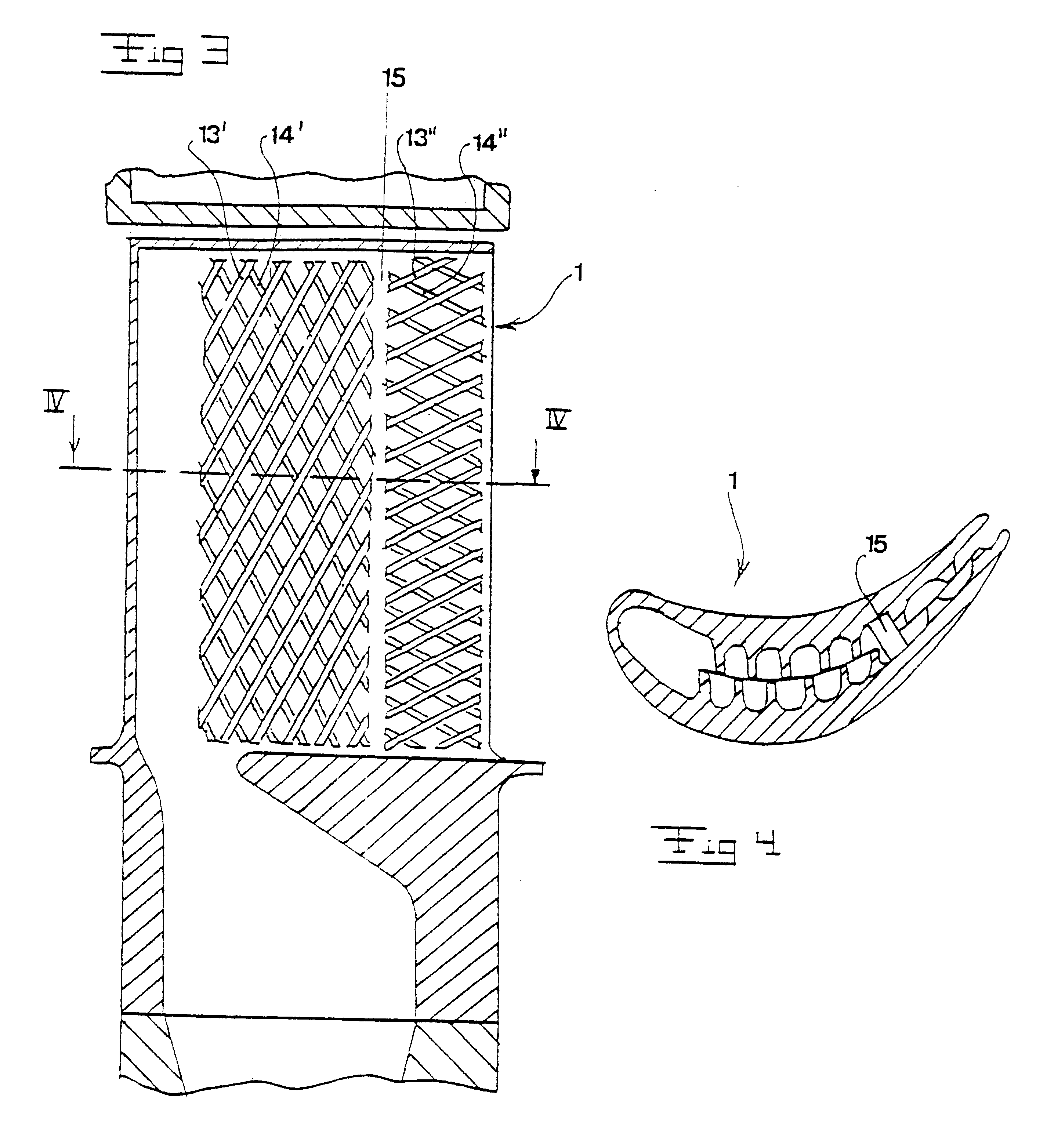
FIGS. 3 and 4 disclose the invention, in which the leading set of ribs 13', 14' are separated from the trailing set of ribs 13", 14" by a gap 15. By such a gap 15, it is possible to distribute the cooling fluid from the flow channels of the leading part 9 uniformly into the flow channels of the trailing part 10.
third embodiment
FIGS. 5 and 6 disclose the invention, in which projecting ribs 16 are provided in the inlet zone 17 of each flow channel of the trailing part 10. By such projecting ribs 16, the turbulences in the flow channels of trailing part 10 may be increased, thereby improving the cooling effect obtained. The ribs 16 extend in a direction essentially perpendicular to the third and fourth directions, respectively.
fourth embodiment
FIGS. 7 and 8 disclose a fourth embodiment, in which projecting ribs 18 are provided to extend in a direction essentially parallel to an inlet edge line 19 of the flow channels of the trailing part 10.
It is to be noted that such projecting ribs 16, 18 or any similar projecting elements also may be provided as an alternative or a complement in the flow channels of the leading part 9. Furthermore, projecting elements may not only be provided in the inlet zone of the flow channels but anywhere in these channels.
The present invention is not limited to the embodiments disclosed but may be varied and modified within the scope of the following claims.
For instance, the ribs 13', 13" and 14', 14", respectively, may extend along a continuous path comprising a curve at which the angle of inclination is changed from the first angle a and third angle c, respectively, to the second angle b and fourth angle d, respectively.
In case that the component is applied to a stator vane, the first ribs may ...
PUM
 Abstract
Description
Claims
Application Information