Supercharge Your Innovation With Domain-Expert AI Agents!

Laser diode driving circuit

a driving circuit and laser diode technology, applied in semiconductor lasers, optical radiation measurement, instruments, etc., can solve the problem of limited number of circuits for biasing laser diodes

Inactive Publication Date: 2002-05-21
IBM CORP
View PDF6 Cites 34 Cited by
  • Summary
  • Abstract
  • Description
  • Claims
  • Application Information

AI Technical Summary

Problems solved by technology

Therefore, the number of circuits for biasing the laser diodes is limited.

Method used


Image

  • Laser diode driving circuit
  • Laser diode driving circuit

Examples


Embodiment Construction

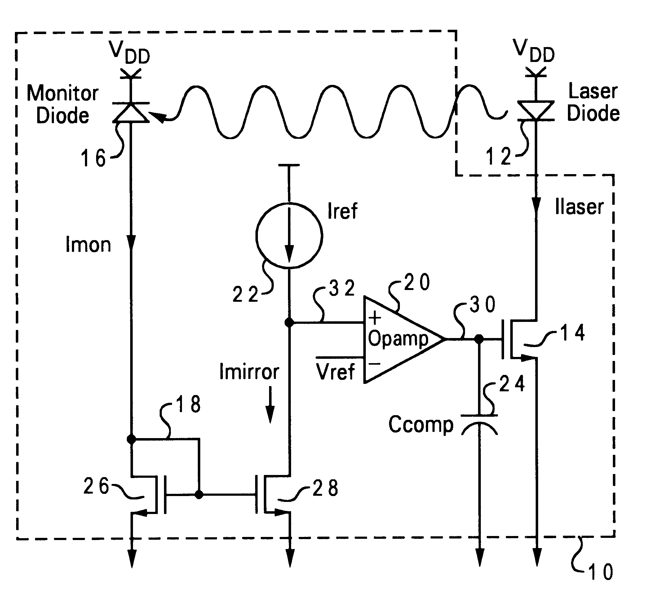
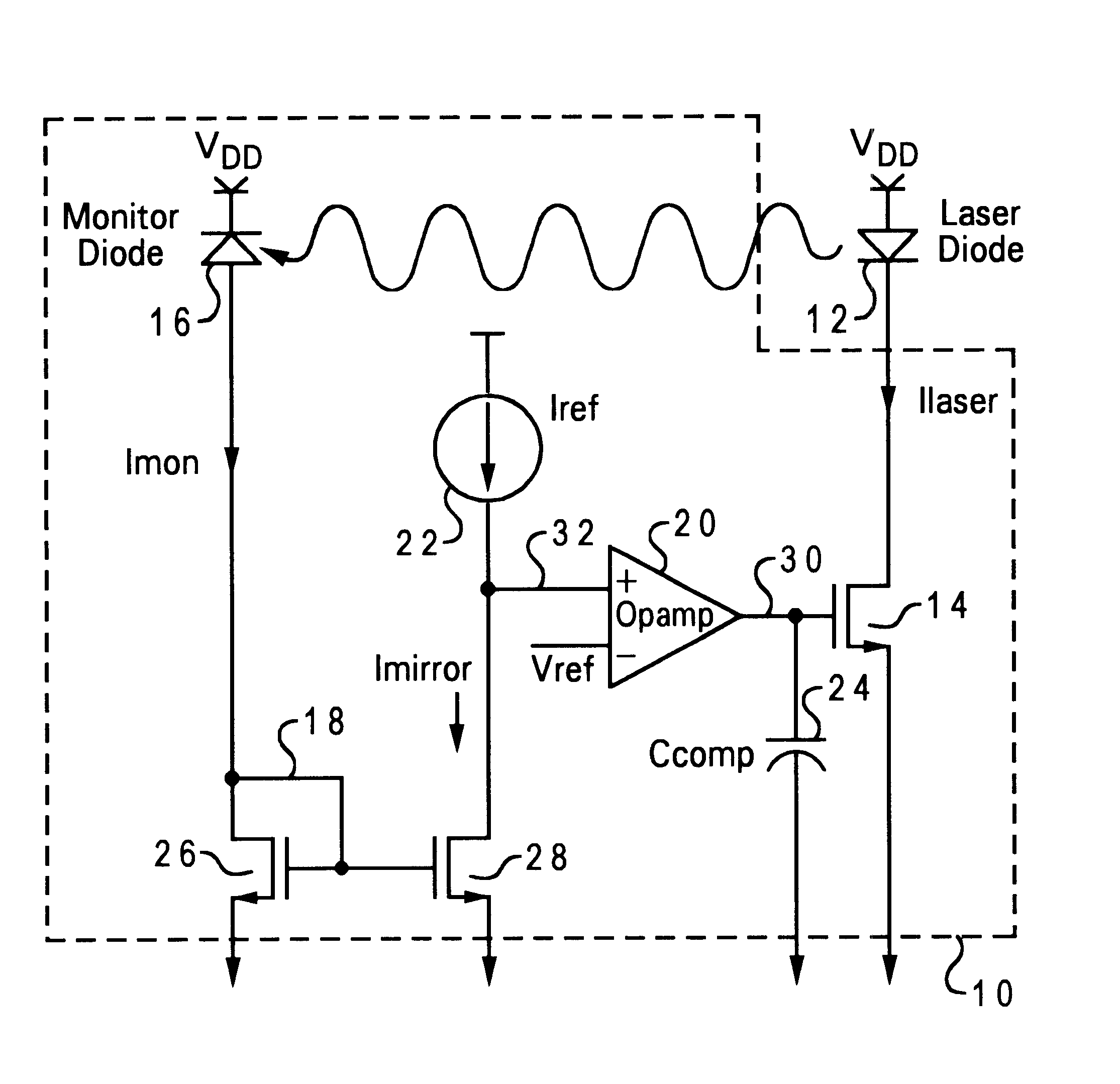
The FIGURE illustrates a schematic diagram of an improved laser diode driver circuit in accordance with the present invention. The present invention is a driver circuit 10 for biasing a semiconductor laser 12. Driver circuit 10 is a feedback loop for automatically adjusting a current source 14 coupled to semiconductor laser 12 for biasing laser 12. Driver circuit 10 is designed to drive a variety of different types of semiconductor lasers, and to automatically adjust the bias current supplied to the laser coupled to driver circuit 10 in order to compensate for the differing characteristics of lasers which may be utilized with circuit 10. Driver circuit 10 is designed to provide a constant laser power output in a low-power environment and to compensate for variations in laser 12 due to temperature variation, aging, and / or variations due to different characteristics of different lasers which may be utilized with driver circuit 10.

Driver circuit 10 includes current source 14, a photode...


PUM


Abstract

An improved laser diode driving circuit is disclosed which includes a current source, an operational amplifier, a light sensing device, a current mirror, and a constant current source. The current source is coupled to the laser diode for biasing the laser diode. The operational amplifier has an output coupled to the current source for driving the current source. The operational amplifier includes a first and a second input. The first input is coupled to a reference voltage. The second input receives a feedback signal. The light sensing device is coupled to a first supply voltage for detecting a portion of an optical power output from the laser. The light sensing device generates a monitor current proportional to the detected optical power output. The current mirror is coupled to the light sensing device and the second input of the operational amplifier. The current mirror receives the monitor current and generates a mirror current which is substantially equal to the monitor current. The constant current source is coupled to the second input of the operational amplifier for outputting a reference current. The reference current and the mirror current are then utilized to generate the feedback signal.

Description

1. Field of the InventionThe present invention relates in general to semiconductor lasers, and, in particular, to an improved laser diode driving circuit. Still more particularly, the present invention relates to an improved laser diode driving circuit for driving a variety of semiconductor lasers.2. Description of the Related ArtReduced scaling or shrinking of the geometries of devices used in integrated semiconductor circuit technology for forming denser circuits has required voltage supply sources to provide lower voltages than the heretofore generally accepted standard supply voltage of 5 volts so as to avoid a voltage breakdown in the smaller devices. These low-power circuits now typically operate in the 3.0 to 3.6 volt supply range.The forward voltage drop of laser diodes has not decreased in proportion to the decrease in the supply voltage. Therefore, the number of circuits for biasing the laser diodes is limited. Further, it is desirable to develop a biasing circuit capable ...

Claims


Application Information

Patent Timeline
Patent Type & Authority Patents(United States)
IPC IPC(8): H01S5/042H01S5/00H01S5/0683
CPCH01S5/0683H01S5/042
Inventor BAUMGARTNER, STEVEN JOHNHEDIN, DANIEL SCOTTSILJENBERG, DAVID WARREN
Owner IBM CORP
Features
  • R&D
  • Intellectual Property
  • Life Sciences
  • Materials
  • Tech Scout
  • Unparalleled Data Quality
  • Higher Quality Content
  • 60% Fewer Hallucinations
Learn More