
Method for dehydrating crude oil and petroleum products and device for realizing the same

Inactive Publication Date: 2002-05-28
OBSHCHESTVO S OGRANICHENNOJ OTVETABTVENNOSTJU SIBMETALLSERVIS
View PDF9 Cites 20 Cited by
  • Summary
  • Abstract
  • Description
  • Claims
  • Application Information

AI Technical Summary

Problems solved by technology

These changes often result in the filtering bed deformation and thus separation worsening, which is obviously a disadvantage of the prototype method.

Method used


Image

  • Method for dehydrating crude oil and petroleum products and device for realizing the same
  • Method for dehydrating crude oil and petroleum products and device for realizing the same

Examples


example 1

Diesel fuel flow containing 10% of emulsified water was passed through the filtering device, load on the filtering element being 11.2 m.sup.3 / m.sup.2.times.h. After filtration water content was 0.01-0.03%, which corresponds to a water removal degree of 95-98.3%. Water content in the diesel fuel before and after filtering was determined with the Dine-Stark method.

example 2

Diesel fuel flow containing 0.24% of emulsified water was passed through the filtering device, load on the filtering element being 10.5 m.sup.3 / m.sup.2.times.h. After filtration water content was less than 0.03%, which corresponds to a water removal degree of not less than 87%. Water content in the diesel fuel before and after filtering was determined with the Dine-Stark method.

example 3

Gasoline containing 0.09 mass. % of emulsified water was passed through the filtering device, load on the filtering element being 18.7 m.sup.3 / m.sup.2.times.h. After filtration no water was detected in gasoline, which corresponds to a 100% water removal. Water content in gasoline before and after filtering was determined with the Fisher method.


PUM

PropertyMeasurementUnit
Electrical resistanceaaaaaaaaaa
Hydrophilicityaaaaaaaaaa
Hydrophobicityaaaaaaaaaa

Abstract

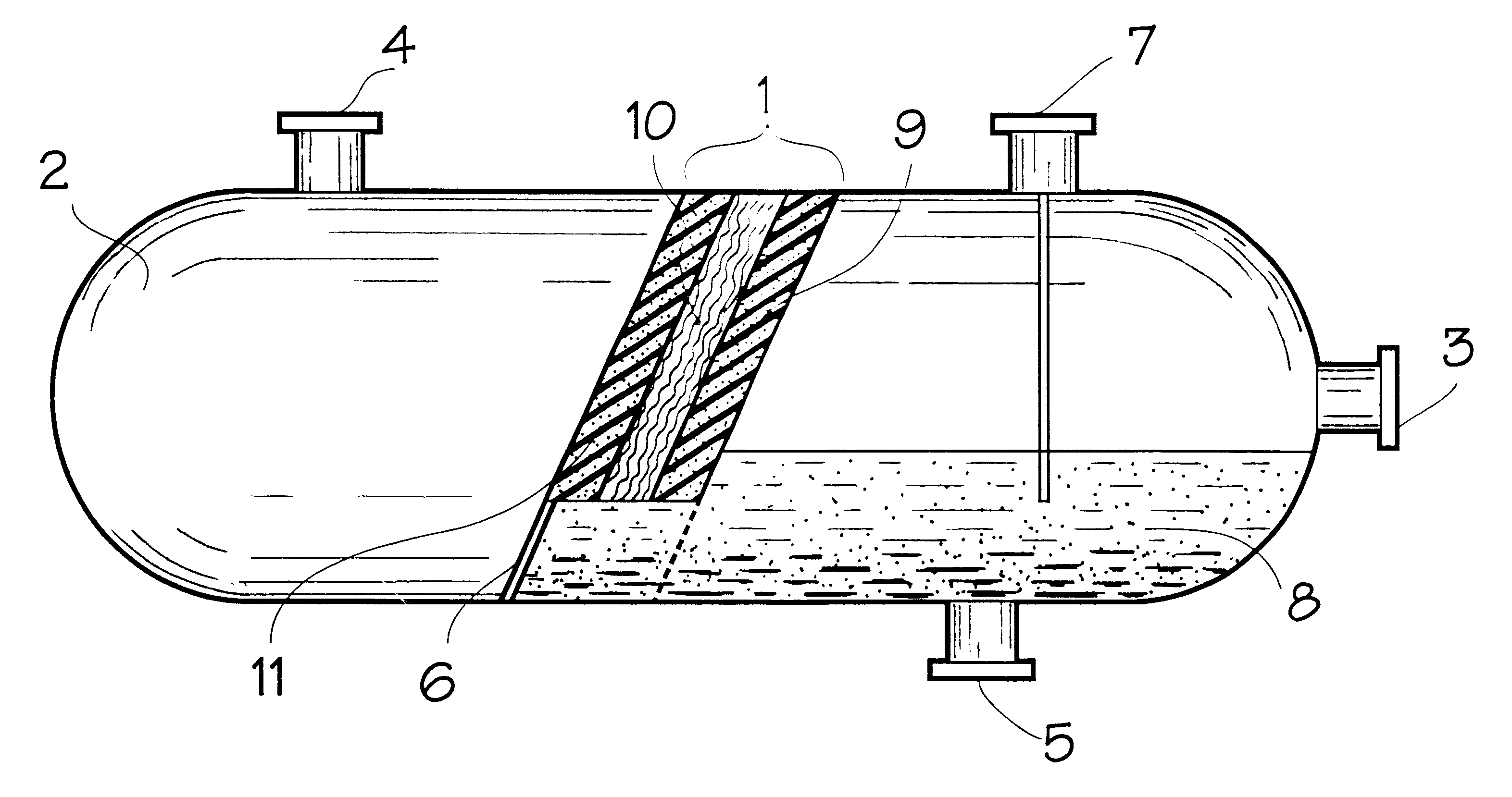
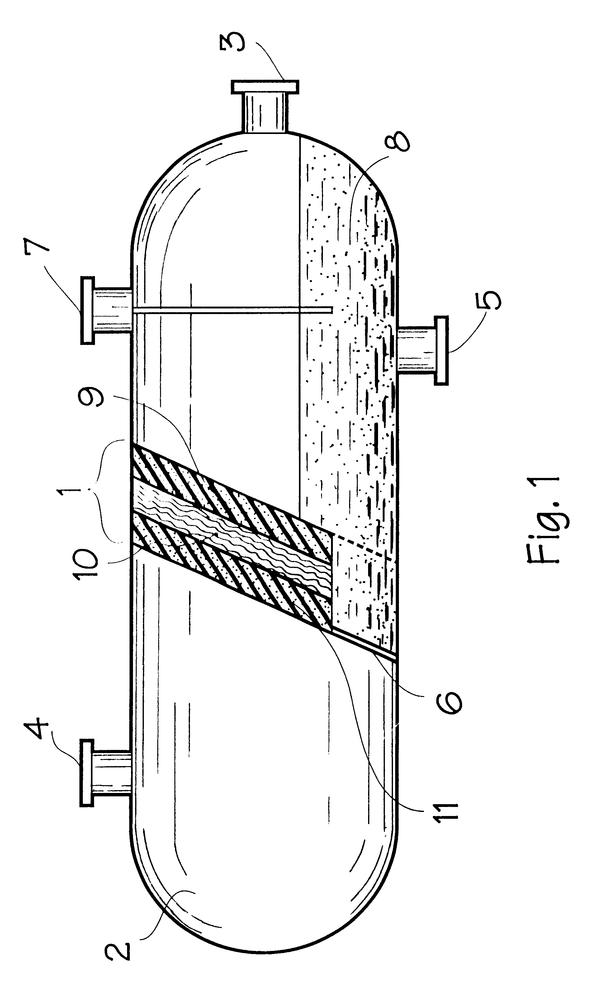
Invention relates to methods for water removal from oil, oil products, gas condensate, and liquid hydrocarbons. The suggested invention aims at a more efficient water removal from the flows of hydrocarbons of different origin. Technical task of water removal is implemented via the selective filtration of hydrocarbons through a filtering element consisting of three tilted beds, wherein the first and the third beds are made of a porous-cellular metal or alloy with hydrophobic surface, while intermediate one is made of hydrophilic materials such as the porous-cellular metal or alloy with modified surface, celluloid foam or the cartridges filled with glass balls or glass fiber. The suggested method allows a high degree of water removal from the hydrocarbon medium under continuous regime without water phase settling. Apparatus for the implementation of this method is also described.

Description

Invention relates to methods for water removal from oil, oil products, gas condense, and liquid hydrocarbons, and to apparatuses for methods implementation.INVENTION BACKGROUNDA method, which is mostly similar to the present invention by dehydration degree, allows the separation of disperse water phase from a hydrocarbon medium by passing the latter through a device containing three beds of filtering materials. In the first and in the third bed the hydrocarbon medium passes through a fibrous polymer material with hydrophobic properties allowing to retain and thus separate disperse water phase. In the second bed finely dispersed water drops are enlarged on a coalescing material (FR 2551671 AI, B 01 D 17 / 04, 1985). However, polymer materials such as polypropylene and polyacrylonitrile, used to separate disperse water phase in the prototype, are known to change their properties, when interacting with hydrocarbons. These changes often result in the filtering bed deformation and thus sep...

Claims


Application Information

Patent Timeline
IPC IPC(8): B01D17/00B01D17/04B01D17/05B01D17/02B01D17/022C10G33/00C10G33/06B01D
CPCB01D17/10C10G31/09Y10S210/05
Inventor BUKHTIYAROV, VALERY IVANOVICHEROKHIN, VYACHESLAV VLADIMIROVICHSERBINENKO, VLADIMIR IVANOVICHSERBINENKO, VLADIMIR VLADIMIROVICH
Owner OBSHCHESTVO S OGRANICHENNOJ OTVETABTVENNOSTJU SIBMETALLSERVIS
Learn More