Optical recording medium and method for making the same

a technology of optical recording medium and optical recording medium, which is applied in the direction of photomechanical equipment, instruments, transportation and packaging, etc., can solve the problems of long time, low productivity, and the rejection of inexpensive resin substrates for heating the overall medium

Inactive Publication Date: 2002-06-04
TDK CORPARATION
View PDF9 Cites 25 Cited by
  • Summary
  • Abstract
  • Description
  • Claims
  • Application Information

AI Technical Summary

Problems solved by technology

However, the initialization step by laser beam illumination takes a long time and is makes the productivity lower.
Heating of the overall medium rejects the use of inexpensive resin substrates.
That is, resin substrates can be distorted upon heating for initialization, causing errors in tracking.
The method of illuminating flash light is also low in productivity because several shots of illumination are necessary to achieve full crystallization.
Initialization of an optical recording disc with a bulk eraser, however, is a time-consuming process, and it takes several minutes just to initialize the optical recording discs of 12 cm diameter.
However, composition of the unit layers is limited in JP-A 106647 / 1996 since it is an object of the JP-A 106647 / 1996 to form a recording in the form of an artificial lattice film.
As a consequence, formation of a recording layer having overall composition optimal for phase change recording is difficult.
In addition, since the unit layers in the recording layer are formed as separate layers, formation of a uniform recording layer is difficult even when the recording layer is initialized by heating, and the medium suffer from insufficiently stable properties.
The medium of U.S. Pat. No. 4,889,746 still suffers from insufficient uniformity of the recording layer due to the formation of the unit layers as separate layers, and therefore, from the insufficiently stable properties.
However, the recording layer formed by such process exhibits unstable degree of erasure as in the case of prior art phase change medium in the overwriting operations from the as-deposited state to several overwriting operations.
In the case of mark edge recording as adopted in rewritable digital video disc (DVD-RAM) and the like, such variation in the reflectance invites erroneous recognition of the mark edge.
It has been, however, found in the further investigation that such medium suffers from inconsistent jitter in the first several overwriting operations.
The current density used in this proposal, however, is considerably high, and such current density can not be used in the mass production in view of the risk of target destruction.
In this process, however, provision of a high-intensity halogen lamp in the vacuum chamber is required, and crystallization of the recording layer with no resin substrate deformation is impossible.

Method used


Image

  • Optical recording medium and method for making the same
  • Optical recording medium and method for making the same

Examples


example 1-1

An optical recording disc was prepared by injection molding polycarbonate into a disc shaped substrate having a diameter of 120 mm and a thickness of 0.6 mm. A groove was formed in one major surface of the substrate simultaneous with injection molding. On the grooved surface of the substrate, there were formed a lower dielectric layer, a recording layer, an upper dielectric layer, a reflective layer, and a protective layer. Another substrate which is the same as the one as described above was further adhered to the protective layer to produce the optical recording disc sample.

The lower dielectric layer was formed by sputtering a target of ZnS and SiO.sub.2. The value of SiO.sub.2 / (ZnS+SiO.sub.2) was 20 mol %. The lower dielectric layer had a thickness of 85 nm.

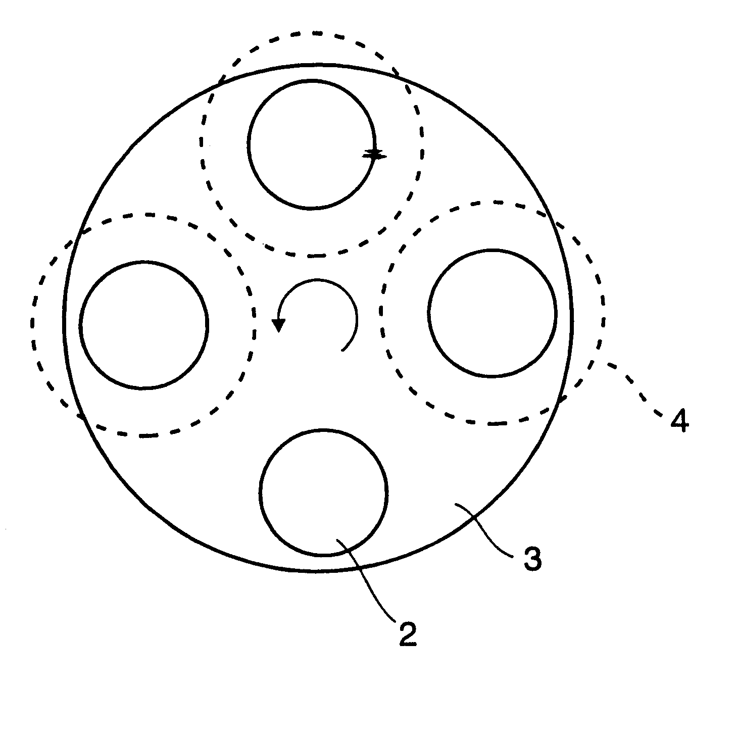
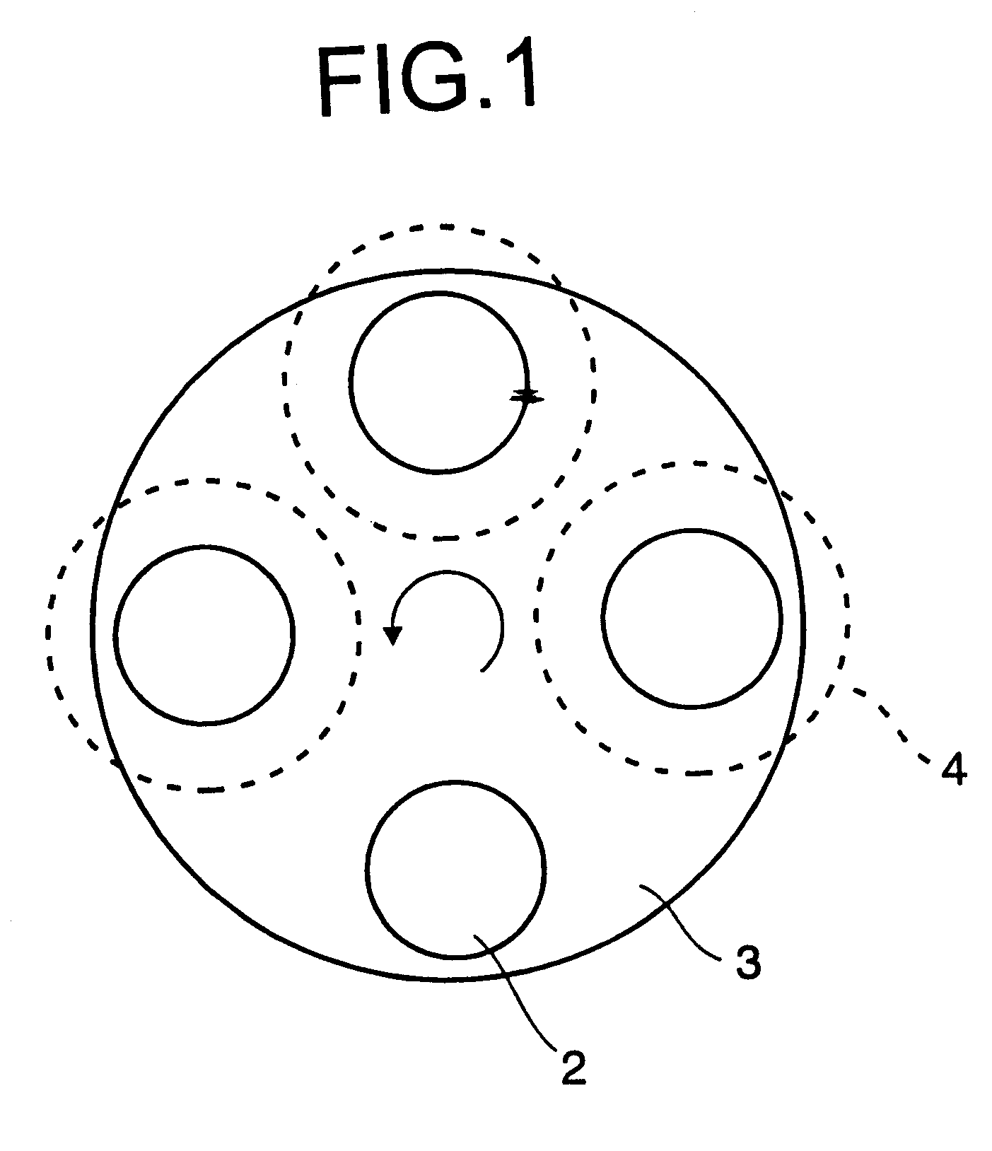
The recording layer was formed by the third procedure of the procedures as described above. FIG. 1 is a plan view schematically showing the sputtering system used. This system has a disc-shaped carousel 3 which is capable of ...

examples 1-2

The procedure of Example 1-1 was repeated except that the rotation speed of the carousel in the formation of the recording layer was set at 6 rpm so that the each disc passes below each target for 3 times. The thus produced sample was evaluated as in the case of Example 1-1. The results are shown in Table 2.

examples 1-3

The procedure of Example 1-1 was repeated except that the rotation speed of the carousel in the formation of the recording layer was set at 4 rpm so that the each disc passes below each target twice. The thus produced sample was evaluated as in the case of Example 1-1. The results are shown in Table 2.


PUM

PropertyMeasurementUnit
thicknessaaaaaaaaaa
crystal grain sizeaaaaaaaaaa
thicknessaaaaaaaaaa

Abstract

In phase change optical recording media wherein initialization process of the recording layer has been the rate determining and cost-increasing factor in the production of the medium, the production cost is reduced by reducing the time required for the initialization and simplification of the initialization process. Stable writing / reading properties are also realized from immediately after the initialization. The present invention provides an optical recording medium comprising a substrate and a recording layer formed over the substrate, wherein the recording layer comprises two or more unit recording layers wherein adjacent two unit recording layers are constituted from different materials and mixture layers between the two adjacent unit recording layers containing all of the elements included in the adjacent two unit recording layers; at least one of the two adjacent unit recording layers is a crystalline layer; and the overall composition of the recording layer falls within the composition of a phase change recording material.

Description

1. Field of the InventionThis invention relates to a phase change optical recording medium and method for making such an optical recording medium.2. Prior ArtHighlight is recently focused on optical recording media capable of recording information at a high density and erasing the recorded information for overwriting. One typical overwritable optical recording medium is phase change optical recording medium wherein a laser beam is directed to the recording layer to change its crystalline state whereupon a change in reflectance by the crystallographic change is detected for reading of the information. The phase change optical recording media are of great interest since the medium can be overwritten by modulating the intensity of a single laser beam and the optical system of the drive unit is simple as compared to magnetooptical recording media.Most optical recording media of the phase change type used Ge--Te systems which provide a substantial difference in reflectance between crysta...

Claims


Application Information

Patent Timeline
Patent Type & Authority Patents(United States)
IPC IPC(8): G11B7/24G11B7/243G11B7/26G11B7/2534G11B7/2542G11B7/257G11B7/2585
CPCG11B7/24G11B7/243G11B7/257G11B7/268G11B7/26G11B7/2534G11B7/2542G11B7/2585Y10T428/21G11B2007/24308G11B2007/2431G11B2007/24314G11B2007/24316
Inventor NAGAYAMA, MORIYOSHINARI, JIRO
Owner TDK CORPARATION
Why Eureka
Try Eureka