Contact switch for an electrical appliance

a technology of contact switch and electrical appliance, which is applied in the field of contact switch, can solve problems such as difficulty in us

Inactive Publication Date: 2002-06-11
E G O ELEKTRO GERAETEBAU GMBH
View PDF16 Cites 51 Cited by
  • Summary
  • Abstract
  • Description
  • Claims
  • Application Information

AI Technical Summary

Benefits of technology

As lighting means preference is given to those with a substantially parallelepipedic housing with a planar top surface on or below which are located the lighting means or through which the latter emit. The lighting means are advantageously light emitting diodes. In a preferred embodiment the illuminated display is a digital d...

Problems solved by technology

The arrangement of such resilient sensor elements, their...

Method used


Image

  • Contact switch for an electrical appliance
  • Contact switch for an electrical appliance
  • Contact switch for an electrical appliance

Examples


Embodiment Construction

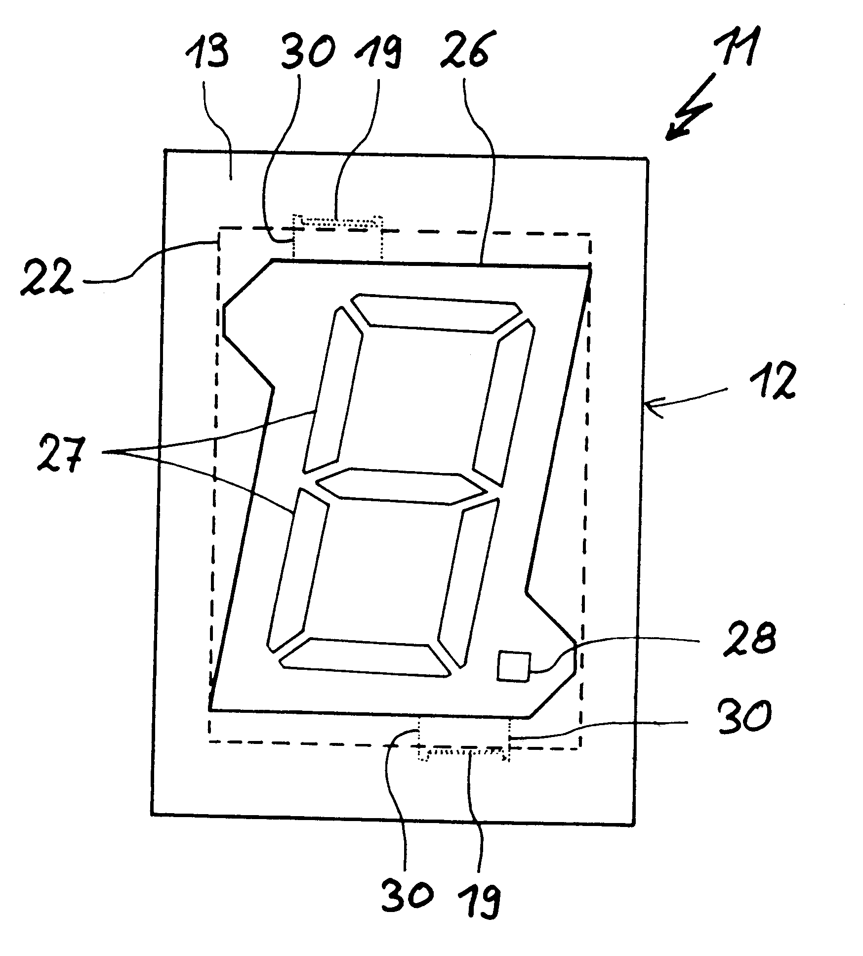
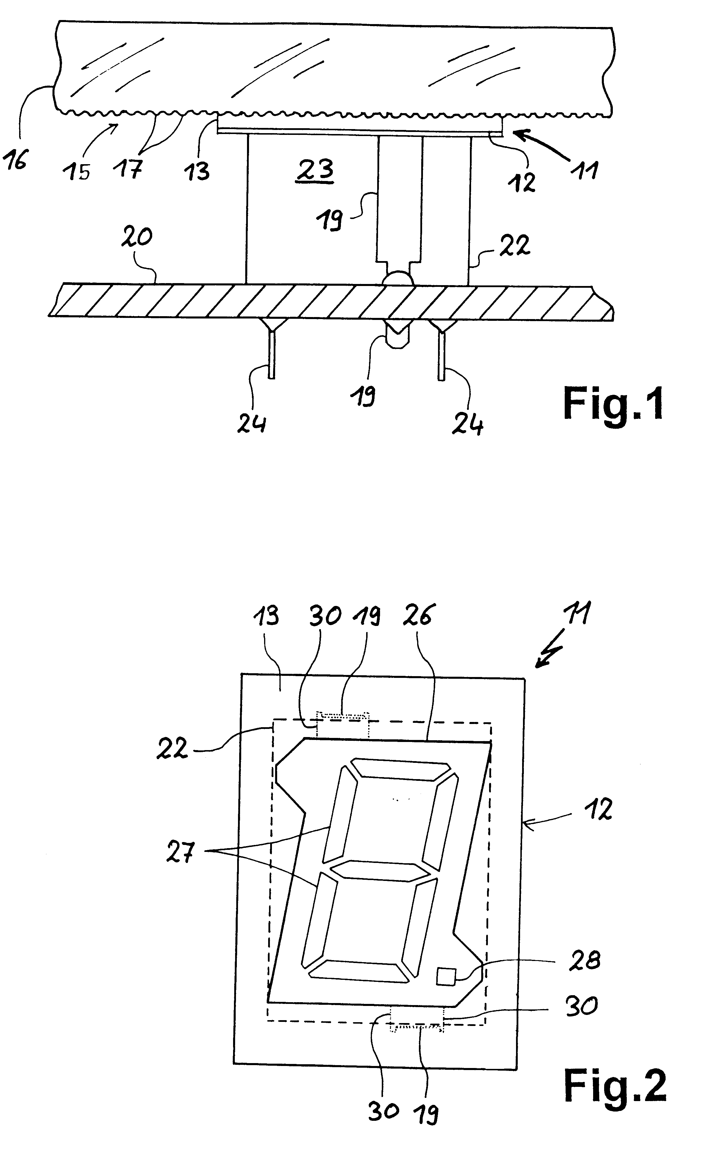
FIG. 1 shows in side view a sensor element 11 having a sensor surface 12, which carries a flexible contact plate 13 in the form of a coating. By means of the elastic contact plate 13 the sensor element 11 is pressed against the underside 15 of a glass ceramic plate 16. The underside 15 has more or less regular studs 17, which can be easily pressed into the contact plate, which can consequently engage flat and substantially without any air gap with the underside 15. In FIG. 1 the thickness of the contact plate 13 has been chosen in such a way that the penetration depth of the studs 17 roughly corresponds to 20% of the thickness.

By means of two standing legs 19 passing from the sensor surface 12 and whereof only the front leg can be seen in FIG. 1, the sensor element 11 is soldered to a printed circuit board 20. Electric contacts and conducting paths are omitted to facilitate ease of understanding. Obviously the printed circuit board can carry these and also further electrical and / or ...


PUM


Abstract

A contact switch having a sensor element with a flat sensor surface, with which is associated an illuminated display in a housing. The sensor surface passes over the housing and has a cutout corresponding to the shape of the lighting means. The sensor surface surrounds the lighting means in a substantially non-overlapping manner and in particular additionally rests on the housing. The sensor surface can also be provided with an elastic, electrically conductive plate for improved adaptation to irregular covers.

Description

The invention relates to a contact switch for an electrical appliance, which has a sensor element with a sensor surface made from flat material and is connected to a control for the sensor element and with it is associated an illuminated display with a housing and lighting means located therein.Contact switches with rectangular, metallic sensor surfaces are known, e.g. conducting paths or surfaces on ceramic supports, which can be resiliently mounted. Such contact switches operate capacitively, which means that the approach or contact of a finger gives rise to a capacitor change on the part of the sensor element, which can be detected. They can be pressed by means of metal springs or the like onto the underside of a cover, e.g. a glass ceramic plate of a cooking area. The arrangement of such resilient sensor elements, their adaptation to a cover and fitting problems make use difficult.OBJECT OF THE INVENTIONThe problem of the invention is to provide a contact switch, which overcomes...

Claims


Application Information

Patent Timeline
IPC IPC(8): H05B3/68H05B3/74H01H9/18H03K17/94H03K17/96G09F9/00H01H13/02H01H9/16H01H13/14
CPCH05B3/74H01H9/181H03K2217/96076H03K17/962
Inventor SCHILLING, WILFRIED
Owner E G O ELEKTRO GERAETEBAU GMBH
Why Eureka
Try Eureka