Carbazole derivative and organic light emitting device using the same

Inactive Publication Date: 2008-06-05
CANON KK
View PDF5 Cites 26 Cited by
  • Summary
  • Abstract
  • Description
  • Claims
  • Application Information

AI Technical Summary

Benefits of technology

[0009]An object of the present invention is to provide a novel carbazole derivative. Another object of the present invention is to provide an organic light emitting device having an optical output with extremely high effic

Problems solved by technology

In addition, many problems still remain to be solved regarding durability against the change over time due to long-term use, deterioration caused by atmospheric gas containing oxygen, moisture, or the like.
F

Method used


Image

  • Carbazole derivative and organic light emitting device using the same
  • Carbazole derivative and organic light emitting device using the same
  • Carbazole derivative and organic light emitting device using the same

Examples


Example

Example 1

Synthesis of Exemplified Compound No. A-25

[0084]

[0085]Compounds described below were each charged into a 300-ml flask.

Compound 1: 3.25 g (10 mmol)

Compound 2: 7.69 g (20 mmol)

Toluene: 50 ml

Ethanol: 25 ml

[0086]2M sodium carbonate solution: 50 ml

Tetrakis(triphenylphosphine)palladium (0): 1 g

[0087]After the charge, agitation was performed at 80° C. for 8 hours under nitrogen flow. After the reaction, the reaction solution was extracted with toluene, and then the organic layer was washed with water. The organic layer was dried with magnesium sulfate and concentrated under reduced pressure. After the purification by silica gel chromatography (eluent: hexane / chloroform), recrystallization was performed with toluene / ethanol to obtain 5.3 g of Compound 3 (yield: 78.0%).

[0088]Next, compounds described below were each charged into a 200-ml flask.

Compound 3: 1.00 g (1.47 mmol)

Iodobenzene: 0.36 g (1.78 mmol)

Ortho-xylene: 70 ml

[0089]Tritertiary butylphosphine: 37 mg

Palladium acetate: 7.6...

Example

Example 2

Synthesis of Exemplified Compound No. A-35

[0096]

[0097]1.00 g (1.47 mmol) of Compound 3, 36 mg of sodium hydroxide, 50 ml of dimethylformamide were each charged into a 100-ml flask, and agitation was performed for 1 hour under nitrogen flow. 0.3 g of methyliodide was dropped thereinto, and the agitation was further performed at room temperature for 5 hours. After the completion of the reaction, the reaction solution was added with methanol and dried and concentrated under reduced pressure. The reaction solution was added with water and extracted with toluene, and dried with magnesium sulfate and concentrated under reduced pressure. After the purification by silica gel chromatography (eluent: toluene), recrystallization was performed with toluene / ethanol. The obtained crystal was dried under vacuum and subjected to sublimation purification to obtain 980 mg of Exemplified Compound No. A-35 (yield: 96.1%).

[0098]Matrix-assisted laser desorption / ionization time-of-flight mass spe...

Example

Example 3

Production of Organic Light Emitting Device

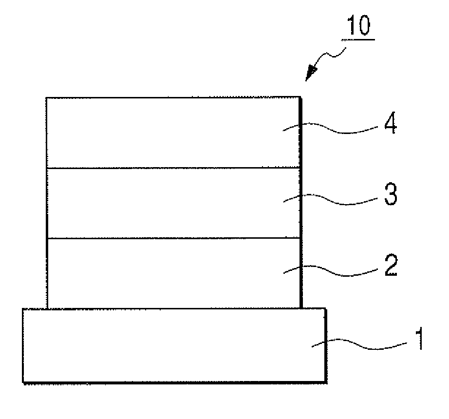
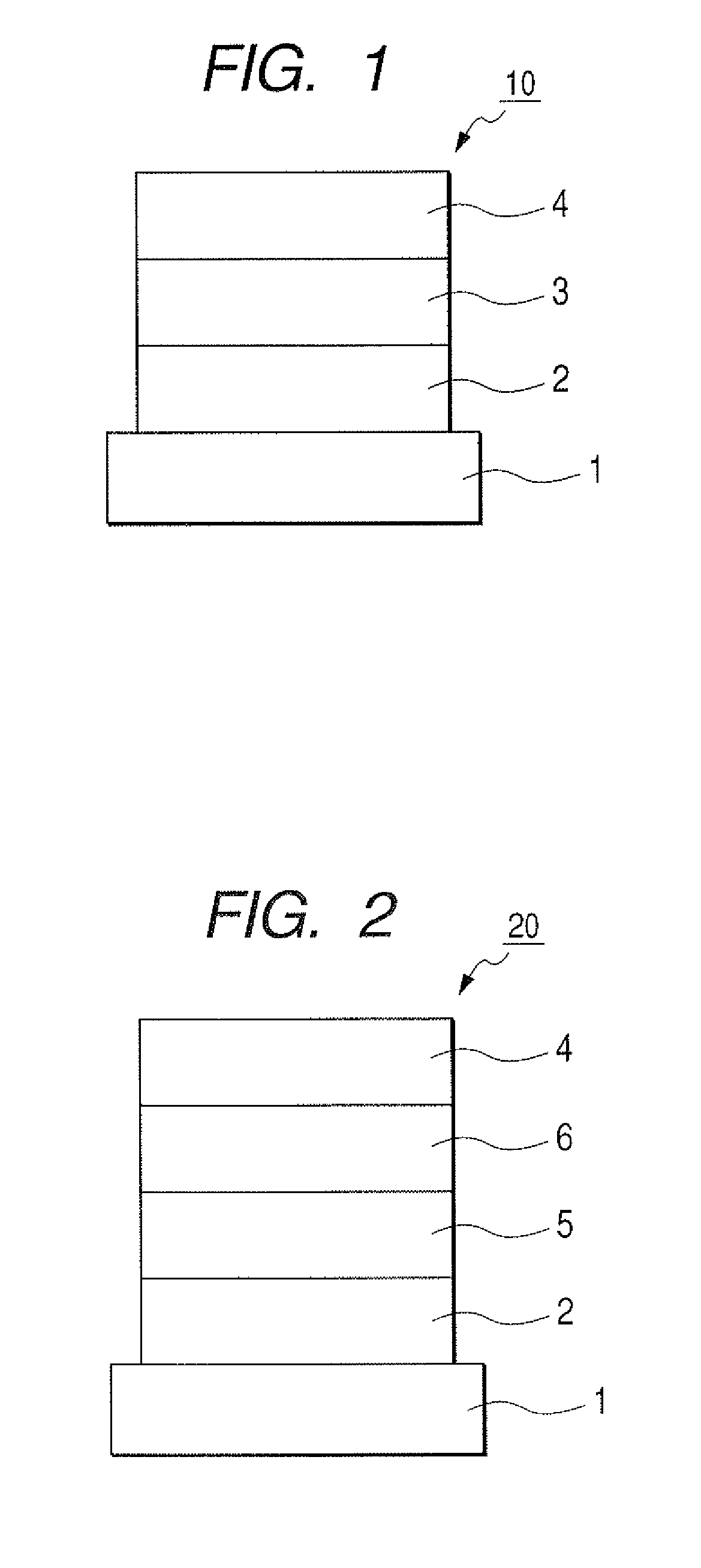
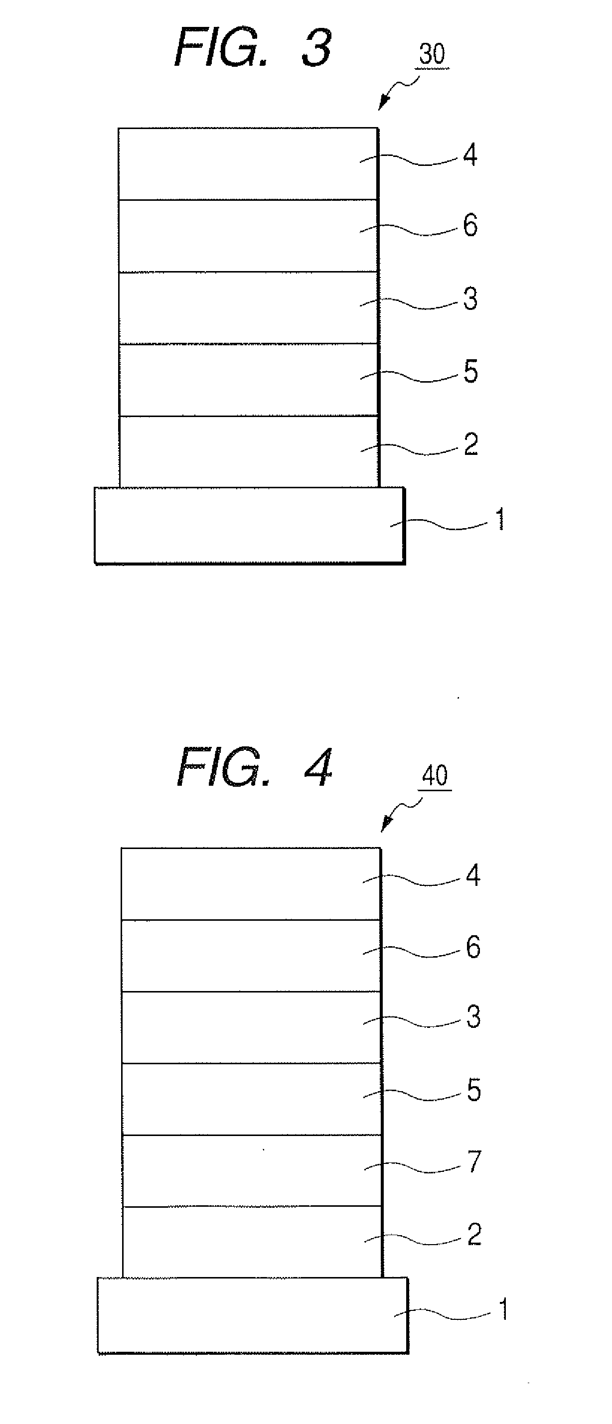
[0101]Indium tin oxide (ITO) was formed by a sputtering method into a film having a thickness of 120 nm to serve as the anode on a glass substrate. The substrate on which ITO film was formed was subjected to ultrasonic cleaning with acetone and isopropyl alcohol (IPA) sequentially. Then, the substrate was subjected to boiling cleaning with IPA, followed by UV / ozone cleaning. Thus treated glass substrate was used as a transparent conductive supporting substrate.

[0102]Chloroform solution of Compound 4 described below was applied onto the transparent conductive supporting substrate by a spin coating method to form a film into a film thickness of 20 nm, thereby obtaining a hole transporting layer. Next, the other organic layer and the electrode layer were successively formed by vacuum vapor deposition using resistive heating within a vacuum chamber of 10−5 Pa. Specifically, first, the light emitting layer was formed into a film thickne...


PUM

PropertyMeasurementUnit
Electric potential / voltageaaaaaaaaaa
Durabilityaaaaaaaaaa
Luminanceaaaaaaaaaa

Abstract

Provided is an organic light emitting device including: a pair of electrodes including an anode and a cathode; and at least one layer formed of an organic compound interposed between the pair of electrodes, in which the at least one layer formed of the organic compound layer contains at least one kind of the carbazole derivative represented by the following general formula (I). The organic light emitting device has an optical output with extremely high efficiency and a high luminance and has an extremely high durability.

Description

BACKGROUND OF THE INVENTION[0001]1. Field of the Invention[0002]The present invention relates to a carbazole derivative and an organic light emitting device using the same.[0003]2. Description of the Related Art[0004]An organic light emitting device is a device in which a thin film including a fluorescent organic compound or a phosphorescent organic compound is interposed between an anode and a cathode. Further, electrons and holes are injected from the respective electrodes to generate exciton of the fluorescent compound or the phosphorescent compound, whereby light is emitted when the exciton return to a ground state is utilized.[0005]According to a study at Eastman Kodak company in 1987 (Appl. Phys. Lett. 51, 913 (1987)), there is reported a device having a function-separation type two-layer structure using ITO as an anode, a magnesium-silver alloy as a cathode, an aluminum quinolinol complex as an electron transporting material and a light emitting material, and a triphenylamine...

Claims


Application Information

Patent Timeline
IPC IPC(8): H01J1/62C07D209/86C07D403/02C07D401/02
CPCH01L51/0072H01L51/006H05B33/14H05B33/20C07D209/86C07D249/08C07D265/38C07D271/07C07D417/04C07D471/04C07D487/22C09K11/06C09K2211/1007C09K2211/1011C09K2211/1014C09K2211/1029H01L51/0054H01L51/5012Y10S428/917H10K85/622H10K85/633H10K85/6572H10K50/11
Inventor IGAWA, SATOSHIOKADA, SHINJIROTAKIGUCHI, TAKAOKAMATANI, JUN
Owner CANON KK
Why Eureka
Try Eureka