Cylindrical electric double-layer capacitor

a double-layer capacitor and cylindrical electric technology, applied in the direction of wound capacitors, electrolytic capacitors, fixed capacitors, etc., can solve the problems of deterioration of the performance, unbalance in the potential to deteriorate the performance,

Inactive Publication Date: 2002-07-02
HONDA MOTOR CO LTD
View PDF4 Cites 12 Cited by
  • Summary
  • Abstract
  • Description
  • Claims
  • Application Information

AI Technical Summary

Problems solved by technology

Therefore, the conventionally known capacitor suffers from a disadvantage that the last-lap annular peripheral surface does not participate in the ensuring of the electrostatic capacity and hence, is useless and a difference between amounts of electrodes utilized for forming the band-shaped positive and negative electrodes causes an unbalance in potential to deteriorate the performance.
On the other hand, however, there is a possibility that the deformation or the like of the band-shaped positive and negative electrodes may occur to deteriorate the performance of the cylindrical electric double-layer capacitor. because the band-shaped positive and negative electrodes are expanded by the charging, as described above.

Method used


Image

  • Cylindrical electric double-layer capacitor
  • Cylindrical electric double-layer capacitor
  • Cylindrical electric double-layer capacitor

Examples


example-3

A cylindrical electric double-layer capacitor 1 having a structure similar to that of the example (2) was produced as a comparative example in the same manner, except that a bottomed cylindrical body 4 having no cylindrical electrode 18 on its inner peripheral surface was used. This cylindrical electric double-layer capacitor 1 is called a comparative example. [Performance of electric double-layer capacitor]

Table 1 shows initial performances of examples (1) and (2) and the comparative example.

It can be seen from Table 1 that there is not a significant difference in internal resistance between examples (1) and (2) and the comparative example, but the electrostatic capacity in each of examples (1) and (2) is about 6% higher than that in the comparative example. This is attributable to that the entire opposite surfaces of the band-shaped positive and negative electrodes 12 and 15 of the electrode winding 3 were utilized effectively for ensuring the electrostatic capacity owing to the p...

embodiment ii

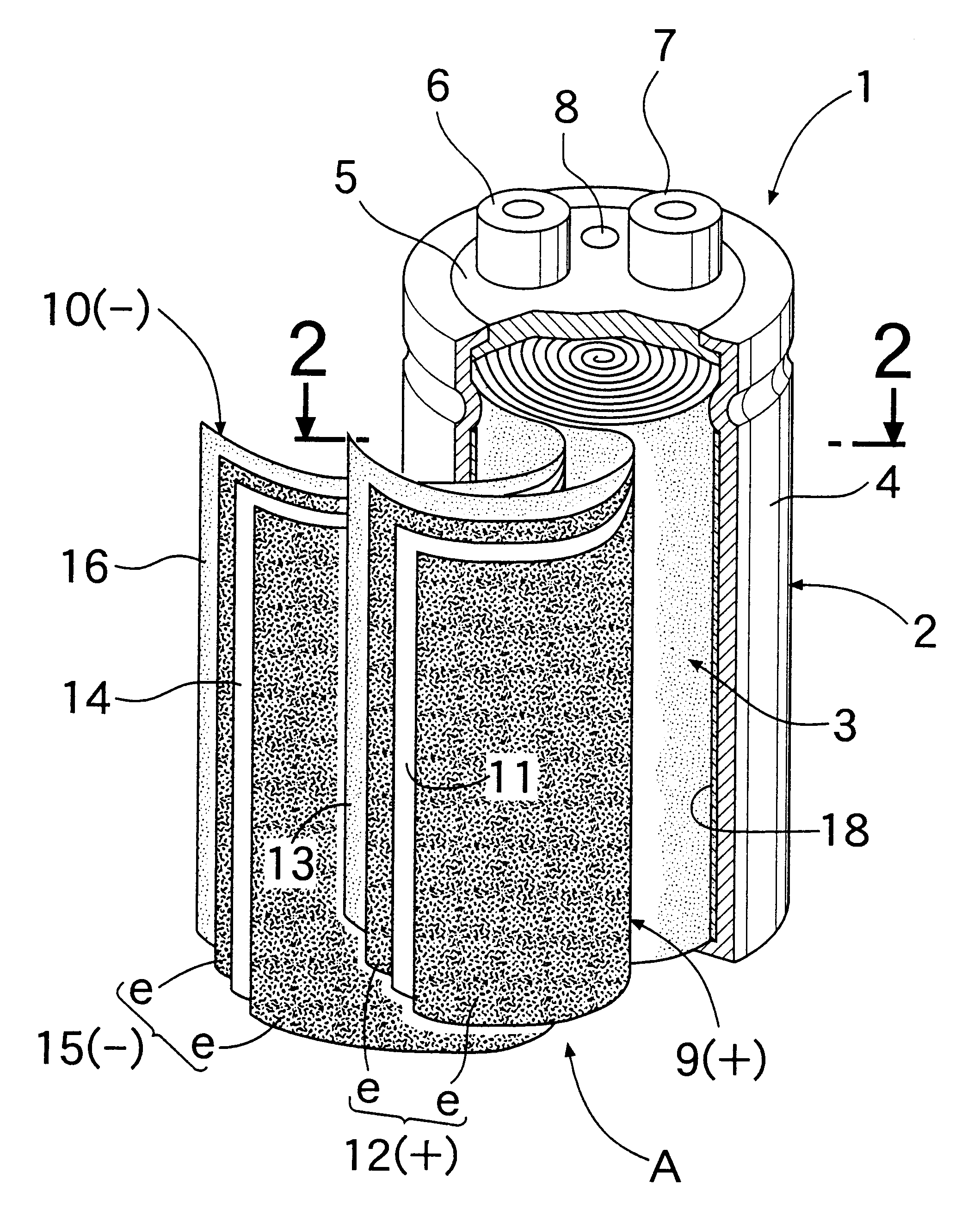
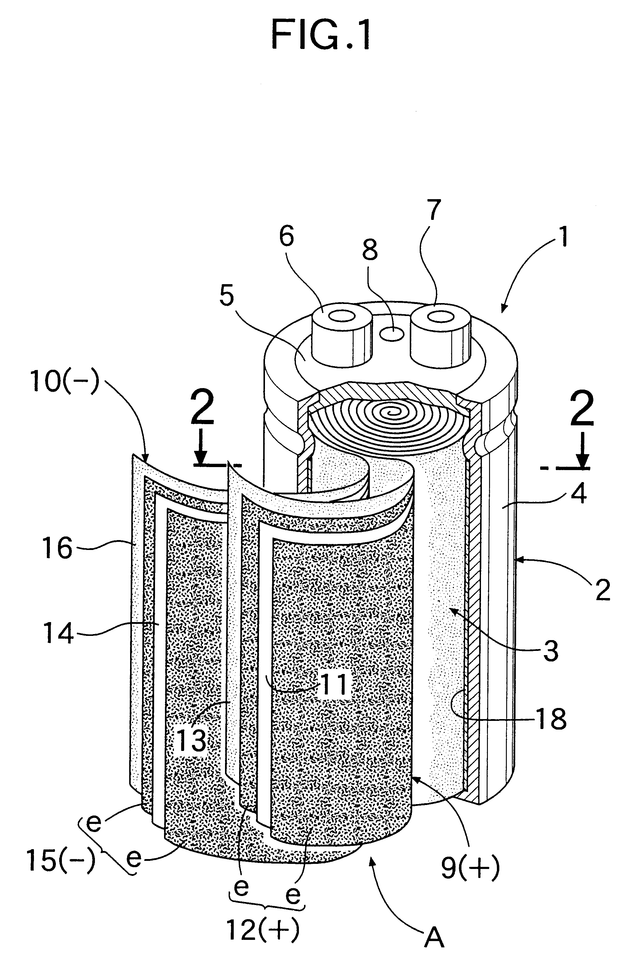
Referring to FIG. 8, a cylindrical electric double-layer capacitor 1 includes a container 2 made of aluminum (Al), an electrode winding 3 accommodated within the container 2, and an electrolyte poured into the container 2. The container 2 comprises a bottomed cylindrical body 4, and a terminal plate 5 which closes an opening in one end of the bottomed cylindrical body 4. Positive and negative terminals 6 and 7 and a safety valve 8 are provided on the terminal plate 5.

The electrode winding 3 has a positive electrode laminated band 9 and a negative electrode laminated band 10. The positive electrode laminated band 9 comprises a band-shaped current colletor 11 made of an aluminum foil and having band-shaped polarizing electrodes e affixed respectively to opposite surfaces thereof by a conductive adhesive, and a first separator 13 made of PTFE (polytetrafluoroethylene) and superposed onto one of the band-shaped polarizing electrodes e. A band-shaped positive electrode 12 is formed by th...

example-1

The KOH-activated carbon powder, a graphite powder (a conductive filler) and PTFE (a binder) were weighed, so that a weight ratio of 85:12.5:2.5 was obtained. Then, the weighed materials were kneaded together, and the kneaded mixture was rolled to produce three electrode sheets having a thickness of 200 .mu.m, 170 .mu.m and 150 .mu.m, respectively. Plurality of band-shaped elements 19, 20 and 21 having a width of 95 mm and a length of 500 mm were cut out from each of the electrode sheets as shown in FIG. 10. A negative electrode laminated band 10 was produced using the three band-shaped elements 19, 20 and 21, a band-shaped current collector 14 having a width of 105 mm, a length of 1,500 mm and a thickness of 40 .mu.m and a conductive adhesive and using a second separator 16 made of PTFE and having a thickness of 75 .mu.m. In this case, each of the band-shaped elements 19 having a thickness of 200 .mu.m was disposed on each of opposite surfaces of the current collector 14 at its len...


PUM


Abstract

A cylindrical electric double-layer capacitor includes an electrode winding which is formed by superposing band-shaped positive and negative electrodes one on another with a first separator interposed therebetween, superposing a second separator onto one of the band-shaped positive and negative electrodes to provide a superposed material, and by spirally winding the superposed material such that the second separator is located on an outermost side, and a container having the electrode winding accommodated therein. A cylindrical electrode is provided on an inner peripheral surface of the container opposed to an outer peripheral surface of the electrode winding. The polarity of the cylindrical electrode is set at a polarity opposite from the polarity of that portion of the band-shaped negative electrode, which is located on an outermost periphery of the electrode winding.

Description

1. Field of the InventionThe present invention relates to a cylindrical electric double-layer capacitor.2. Description of the Related ArtThere is a conventionally known cylindrical electric double-layer capacitor including an electrode winding which is formed by superposing a band-shaped positive electrode and a band-shaped negative electrode one on another with a first separator interposed therebetween, superposing a second separator onto one of said band-shaped positive and negative electrodes to provide a superposed material and by spirally winding the superposed material such that the second separator is located on an outermost side, and a container having the electrode winding accommodated therein. In this case, in the electrode winding, that portion of one of the band-shaped positive and negative electrodes, which is located on an outermost periphery, namely, a last-lap annular outer peripheral surface, has no mating electrode opposed thereto.Therefore, the conventionally know...

Claims


Application Information

Patent Timeline
Patent Type & Authority Patents(United States)
IPC IPC(8): H01G9/00H01G9/155
CPCH01G9/155Y02E60/13H01G11/52H01G9/02H01G4/32
Inventor OYAMA, SHIGEKINOGUCHI, MINORU
Owner HONDA MOTOR CO LTD
Why Eureka
Try Eureka