

Ground advance shoring system
a technology of shoring system and ground advance, which is applied in the direction of bridges, roads, roads, etc., can solve the problems of considerable waste of concrete materials, time-consuming installation or dismantling of supporting frames, and construction methods that require a considerable amount of materials for supporting frames, so as to reduce the number of supporting units required in this invention, the effect of reducing the time for installation
- Summary
- Abstract
- Description
- Claims
- Application Information
AI Technical Summary
Benefits of technology
Problems solved by technology
Method used
Image


Examples
Embodiment Construction
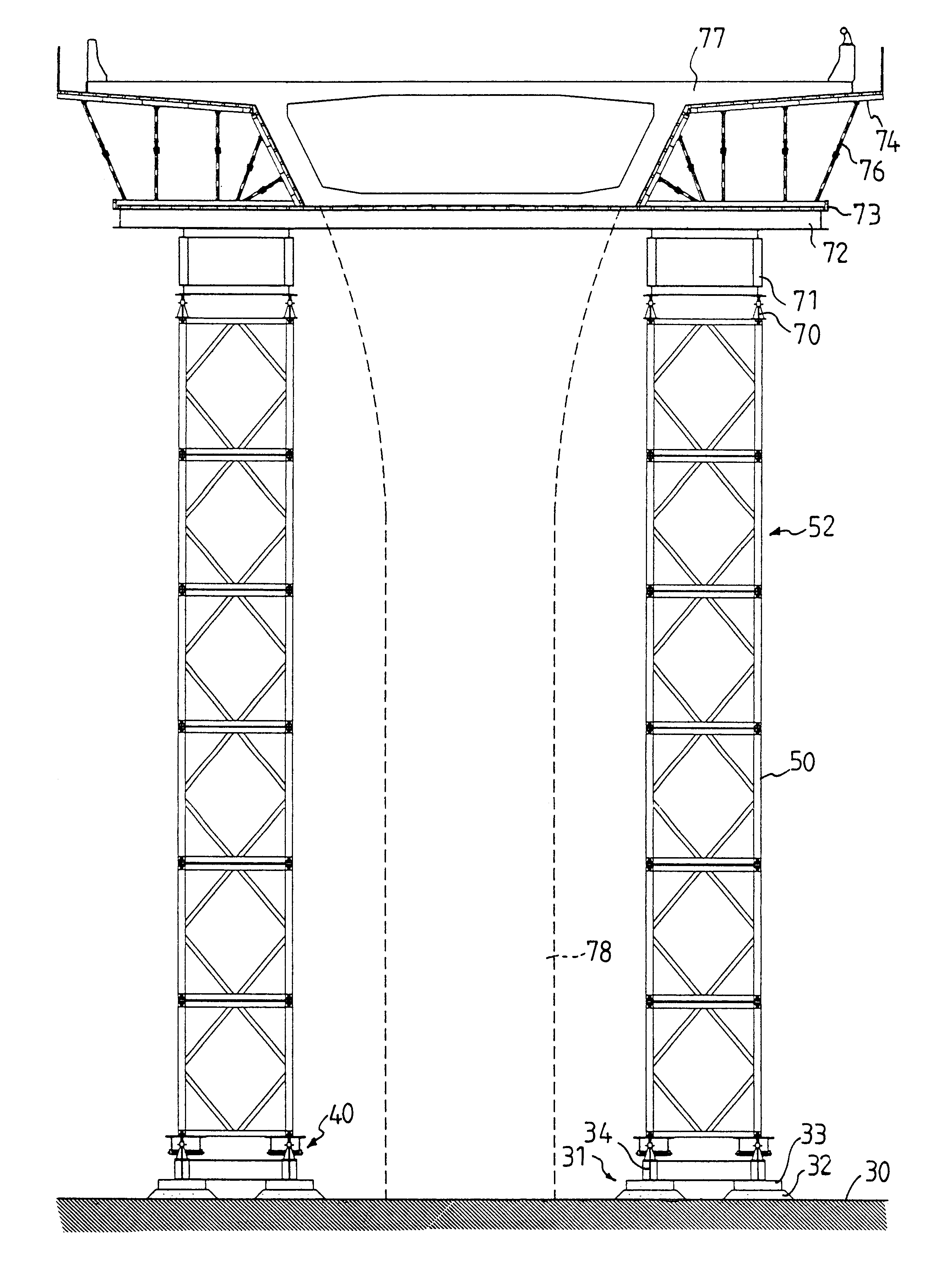
This invention is related to a ground advance shoring system and the construction method using such a system. Detailed description of the preferred embodiments according to this invention is provided in association with the drawings. The system according to this invention, as illustrated in FIGS. 6 and 7, generally comprises a railway assembly 31 which is provided on the ground 30. The railway assembly 31, as shown in FIG. 8, includes aggregate 32, such as gravel, paved on the ground 30, lining plates 33 covered on the aggregate 32, and railways 34 placed on the lining plates 33. In the preferred embodiment of this invention, the railways 34 are constructed by longitudinal and traverse steel H-beams. The system according to this invention further comprises at least one movable device 40, as shown in FIGS. 9-11, which includes a moving platform 43 and. can be moved on the railway assembly 31. In the preferred embodiment of this invention, a plurality of wheels 41 and at least one bot...
PUM
 Abstract
Description
Claims
Application Information