
Microdosing device

a microdosing device and microdosing technology, which is applied in the direction of positive displacement liquid engines, laboratory glassware, instruments, etc., can solve the problems of limited dosing accuracy in the case of smaller volumes, only possible drop generation in a very limited viscosity range, and high dosing accuracy

Inactive Publication Date: 2002-07-09
ZYRUS BET GMBH & CO PATENTE I KG +1
View PDF12 Cites 55 Cited by
  • Summary
  • Abstract
  • Description
  • Claims
  • Application Information

AI Technical Summary

Benefits of technology

This object is achieved by a volume sensor-free microdosing device comprising a pressure chamber which is at least partly delimited by a displacer, an actuating device for actuating the displacer, the volume of the pressure chamber being adapted to be changed by actuating the displacer, a media reservoir which is in fluid communication with the pressure chamber, an outlet opening which is in fluid communication with the pressure chamber, and a control means. With the aid of the control means the microdosing device is driven in such a way that a small change of volume is effected per unit time by a movement of the displacer from a first position to a predetermined second position, the second position of the displacer defining a larger volume of the pressure chamber than the first position, so as to suck a fluid volume into the pressure chamber. During a second phase, the control means drives the microdosing device in such a way that, by means of a movement of the displacer from the second position to the first position, a large volume change of the pressure chamber volume is effected per unit time so as to eject a defined fluid volume from the outlet opening in this way.
According to the present invention, fluid is ejected due to a direct displacement of the fluid, in contrast to acoustic principles which are used in most ink printheads. In such ink printheads, especially in printheads which are driven piezoectrically, a pressure wave is normally produced in the dosing chamber which propagates in the direction of the nozzle and which causes the drop to tear at the nozzle. The drop diameter will here essentially correspond to twice the cross-section of the nozzle. In contrast to this, a pressure wave is generated by a vapour bubble in known, so-called bubble jet printers; the displacement caused by the vapour bubble is limited to a volume of approx. 50 to 100 pl due to the size of the vapour bubble and cannot be substantially increased due to physical principles. This will typically have the effect that an individual drop having a size of the order of twice the cross-section of the nozzle will tear, whereas according to the present invention a jet of fluid is obtained whose total volume is much larger than this individual drop.
As has already been explained, an essential advantage of a dosing process according to the present invention is to be seen in the fact that a fluid jet as a whole is discharged and that there is no need of adding a plurality of individual drops for obtaining the desired dosing volumes e.g. in the field of biotechnology. Although the exact tearing of the free jet at the outlet opening is influenced by the properties of the media, as in the case of conventional systems, a higher dosing accuracy is still obtained according to the present invention. Since the media displacer of the microdosing device according to the present invention is easily able to discharge also larger volumes in the desired range between 0.01 .mu.l and 0.1 .mu.l in the course of a process, volume errors, which are a result of the tearing of the individual drops and which would represent a comparatively large relative error in the case of drop volumes of 0.0001 .mu.l, are no longer of any importance. A summation of the systematic errors per drop no longer occurs according to the present invention.

Problems solved by technology

The limited dosing accuracy in the case of smaller volumes is predominantly due to the fact that the tip of the pipette or dispenser must be immersed into the medium to be dosed, whereby the dosing amount will be influenced by effects such as surface tension, wetting and hydrostatic pressure.
However, the viscosity and the surface tension substantially influence the size of the drops and, consequently, the volume dosed.
Furthermore, a generation of drops is only possible in a very limited viscosity range.
Since the volume errors of the individual drops will, however, accumulate in this process, the dosing accuracy is strongly limited.
An increase of this dosing accuracy is only possible with the aid of complicated and expensive systems.
It is, however, easily evident that the above-mentioned methods of increasing the dosing accuracy are both very complicated and expensive.
Hence, the relative dosing error of the total volume corresponds to the relative dosing error of each individual drop.
This will, however, no longer have any influence on the total dosing amount, since the fluid has already left the nozzle.
This is another possibility of causing a small volume change of the pressure chamber volume per unit time when the displacer moves from the first position to the second position.

Method used


Image

  • Microdosing device
  • Microdosing device
  • Microdosing device

Examples


Embodiment Construction

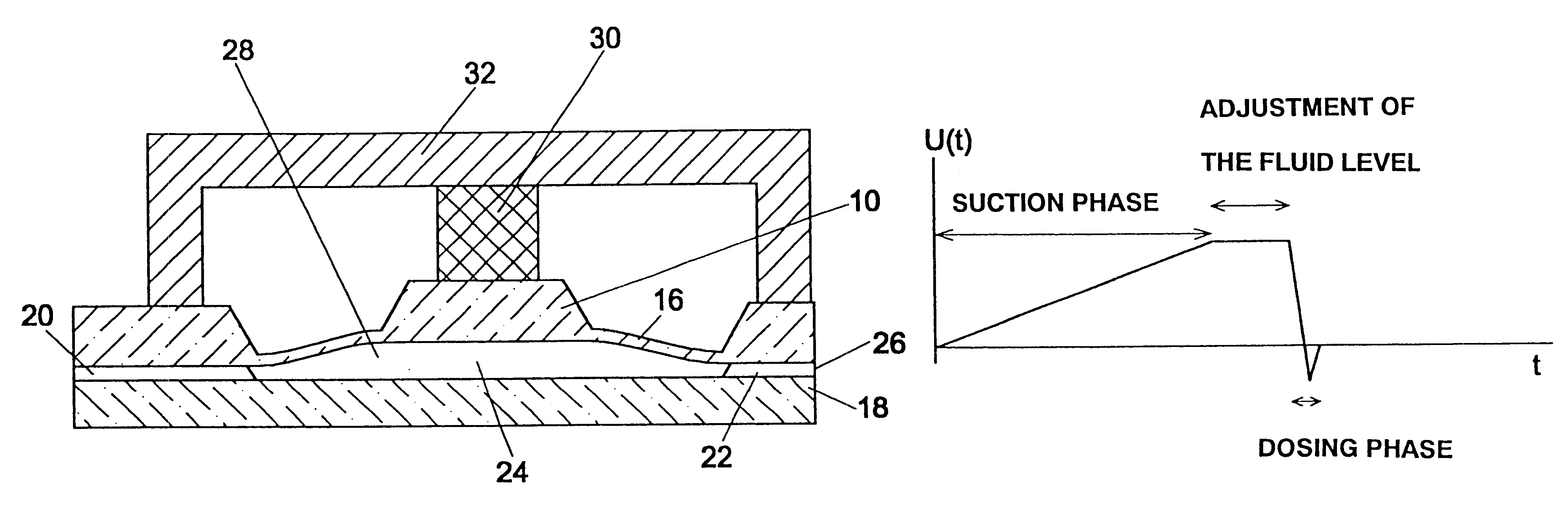
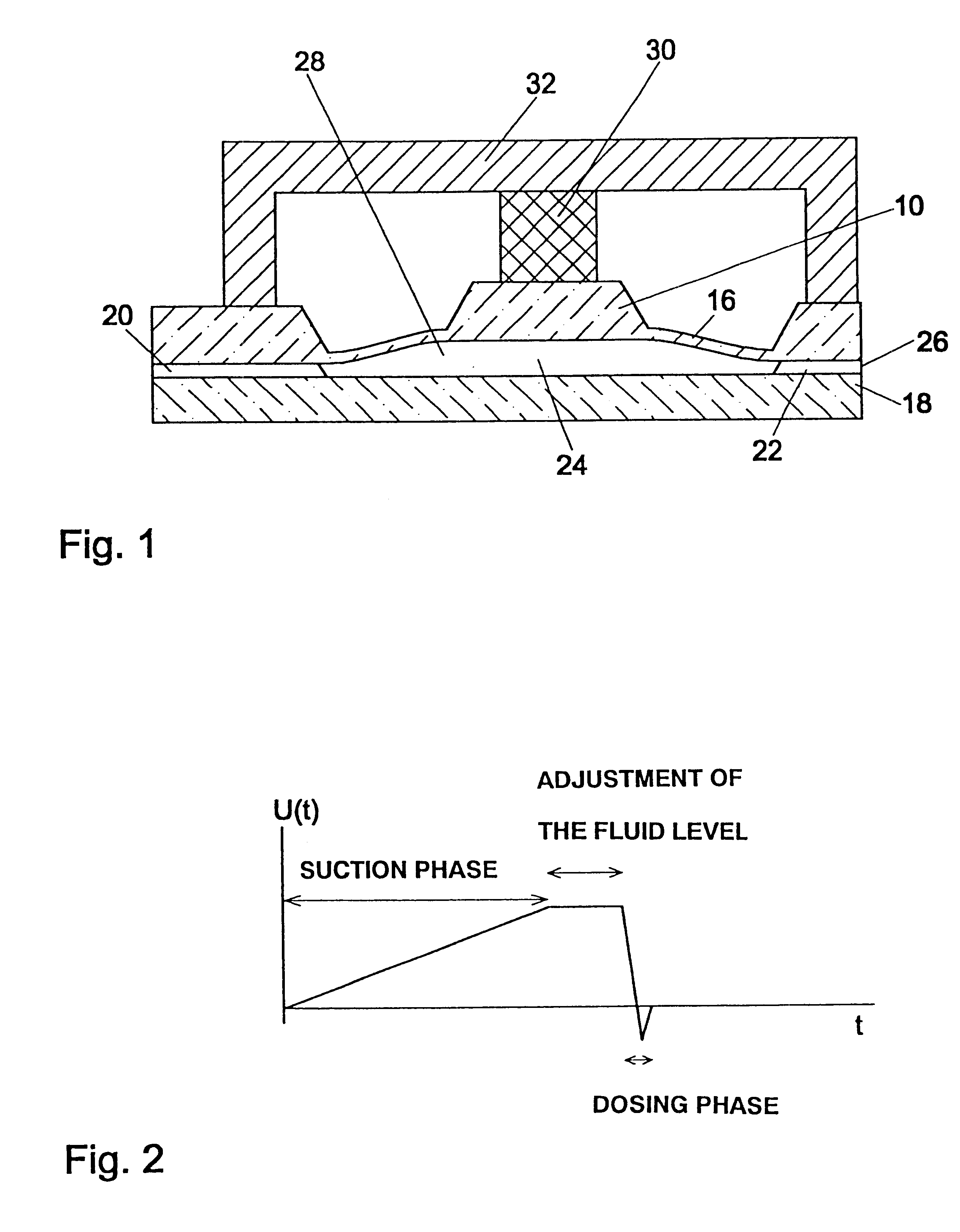
FIG. 1 shows a possible embodiment of the microdosing device according to the present invention, which is particularly suitable for producing the dosing element by means of semiconductor-technological methods. In the embodiment shown, the media displacer 10 is realized as a stiffened membrane which is etched in silicon. The displacer structure is produced by means of anisotropic KOH etching which results in the trapezoidal recesses defining the membrane 16. In addition to a stiffened membrane, it is also possible to use a non-stiffened membrane.

In the embodiment of the present invention shown in FIG. 1, the displacer structure 10 is connected to a Pyrex glass plate 18 by means of anodic bonding. In the preferred embodiment, recesses are provided in the silicon wafer in which the displacer structure 10 is defined, the recesses defining a reservoir channel 20, a nozzle channel 22 and a pressure chamber 24. The nozzle channel 22 is in fluid communication with an outlet opening 26, whic...


PUM


Abstract

A volume sensor-free microdosing device comprises a pressure chamber which is at least partly delimited by a displacer, an actuating device for actuating the displacer, the volume of the pressure chamber being adapted to the changed by actuating the displacer, a media reservoir which is in fluid communication with the pressure chamber, an outlet opening which is in fluid communication with the pressure chamber, and a control mechanism. The control mechanism drives the microdosing device in such a way that a small change of volume of the pressure chamber volume is effected per unit time by a movement of the displacer from a first position to a predetermined second position, the second position of the displacer defining a larger volume of the pressure chamber than the first position, so as to suck a fluid volume into the pressure chamber, and that, in a second phase, a large volume change of the pressure chamber volume is effected per unit time by a movement of the displacer from the second position to the first position, so as to eject a defined fluid volume from the outlet opening in this way.

Description

PRIORITYApplicants claim the benefit of priority from International Application PCT / EP99 / 00185.1. Field of the InventionThe present invention relates to a microdosing device.2. Description of Prior ArtPrecise dosing of extremely small volumes of fluid in the range between 0.01 .mu.l and 1 .mu.l is of great and decisive importance e.g. in the fields of biotechnology, DNA analytical chemistry and combinatorial chemistry. According to the prior art, dispensers or pipettes are predominantly used for dosing small volumes. In these cases, the volume to be dosed is displaced either directly, by a so-called piston-type direct displacement, or via an intermediate air cushion. In this respect, reference is made e.g. to the article "Pipettieren und Dispensieren", A. Jahns, Fachzeit-schrift der Technischen Assistenten in der Medizin, volume 8 (1993), No. 12, pages 116-1172, Umschau Zeitschriftenver-lag.Air-cushion pipettes are suitable for dosing volumes between 0.01 .mu.l and 5 ml, accuracies ...

Claims


Application Information

Patent Timeline
IPC IPC(8): B01L3/02F04B43/02F04B43/04G01F11/08G01F11/02G01N35/10G01N35/00B01J4/00G01N31/20B05B9/04C40B60/14F04B19/00
CPCB01L3/0268F04B43/046G01F11/08G01N35/1016B01J2219/00351B01J2219/00378B01L3/0203B01L2400/0481C40B60/14G01N2035/00237
Inventor ZENGERLE, ROLANDFREYGANG, MICHAELHEY, NICOLAUSGRUHLER, HOLGER
Owner ZYRUS BET GMBH & CO PATENTE I KG
Learn More