Erosion compensated magnetron with moving magnet assembly

a technology of moving magnets and magnets, applied in the direction of electrodes, diaphragms, ion implantation coatings, etc., can solve the problems of not being able to extend easily to other geometries and movements, and affecting the effect of ion implantation

Inactive Publication Date: 2002-07-09
BEKAERT ADVANCED COATINGS
View PDF19 Cites 64 Cited by
  • Summary
  • Abstract
  • Description
  • Claims
  • Application Information

AI Technical Summary

Benefits of technology

Further, it is an object of the present invention to provide a simple erosion profile compensation device particularly for a planar magnetron.
The present invention may provide the advantages of good utilisation of target materials while still providing a mechanically simple and reliable magnet assembly and drive.

Problems solved by technology

U.S. Pat. No. 5,417,833 discusses previous attempts to achieve uniform target erosion and points out that minor changes in the shape of the magnet array can lead to dramatic changes in erosion profiles.
It is pointed out that it is difficult to marry actual magnetron results with strict mathematical analysis, the interaction of plasma with magnetic and electric fields not being a trivial problem.
Further, the teachings of U.S. Pat. No. 5,417,833 are related to a very special magnet array geometry and cannot be extended easily to other geometries and movements.
This is not easy with an electromagnet and hence, it is generally not possible to compensate for moving magnetic fields with changing magnetic field vector with an electromagnet particularly when the geometry of the magnet array and / or the motion of the magnet array is complex.

Method used


Image

  • Erosion compensated magnetron with moving magnet assembly
  • Erosion compensated magnetron with moving magnet assembly
  • Erosion compensated magnetron with moving magnet assembly

Examples


Embodiment Construction

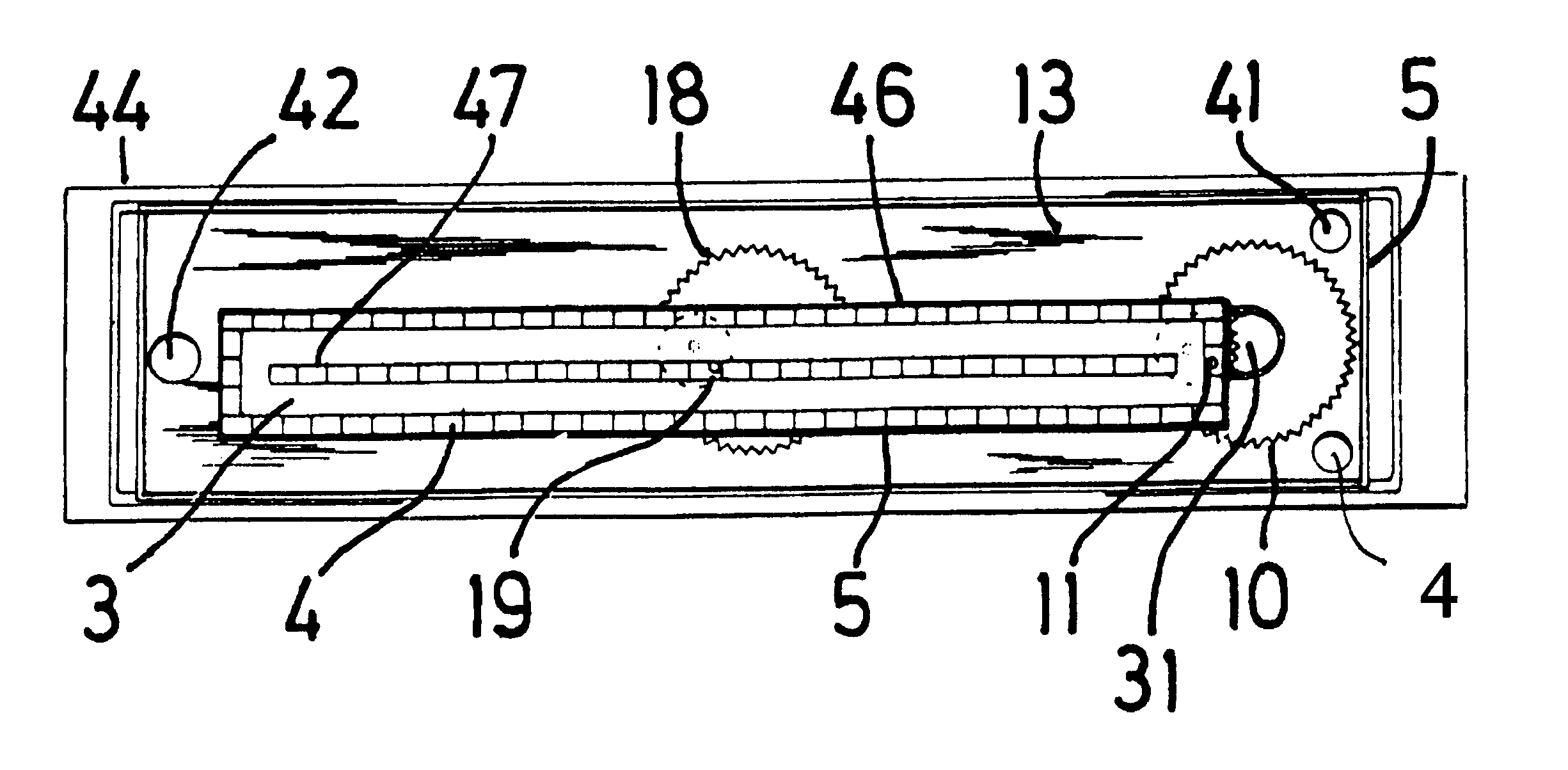
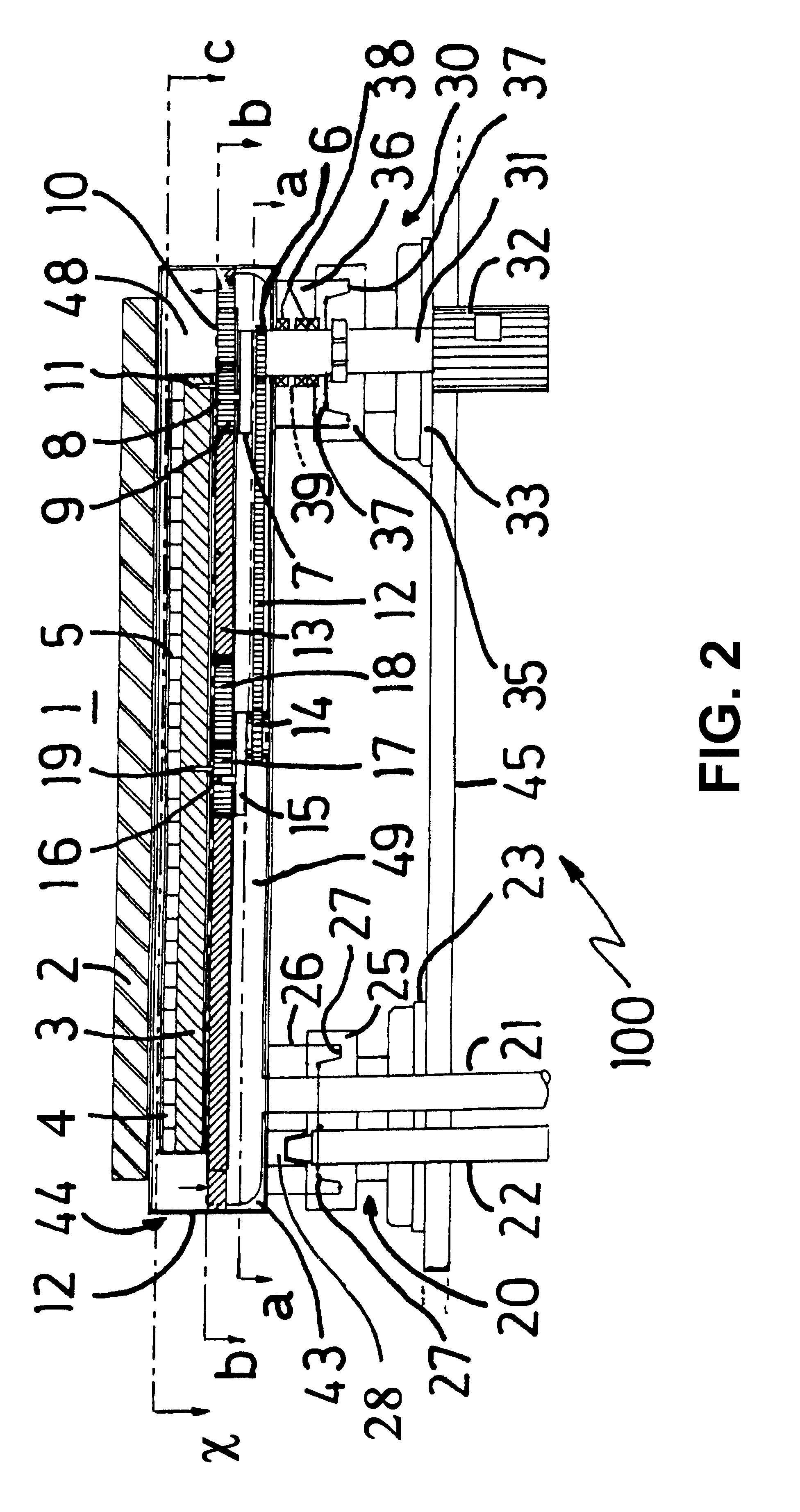
The present invention will be described with respect to particular embodiments and with reference to certain drawings but the invention is not limited thereto but only by the claims. The drawings described are only schematic and are non-limiting. The present invention will mainly be described with reference to a planar magnetron however, the present invention is not limited thereto but may find advantageous use in any kind of sputtering magnetron, e.g. rotating cathode magnetrons, as defined in the appended claims.

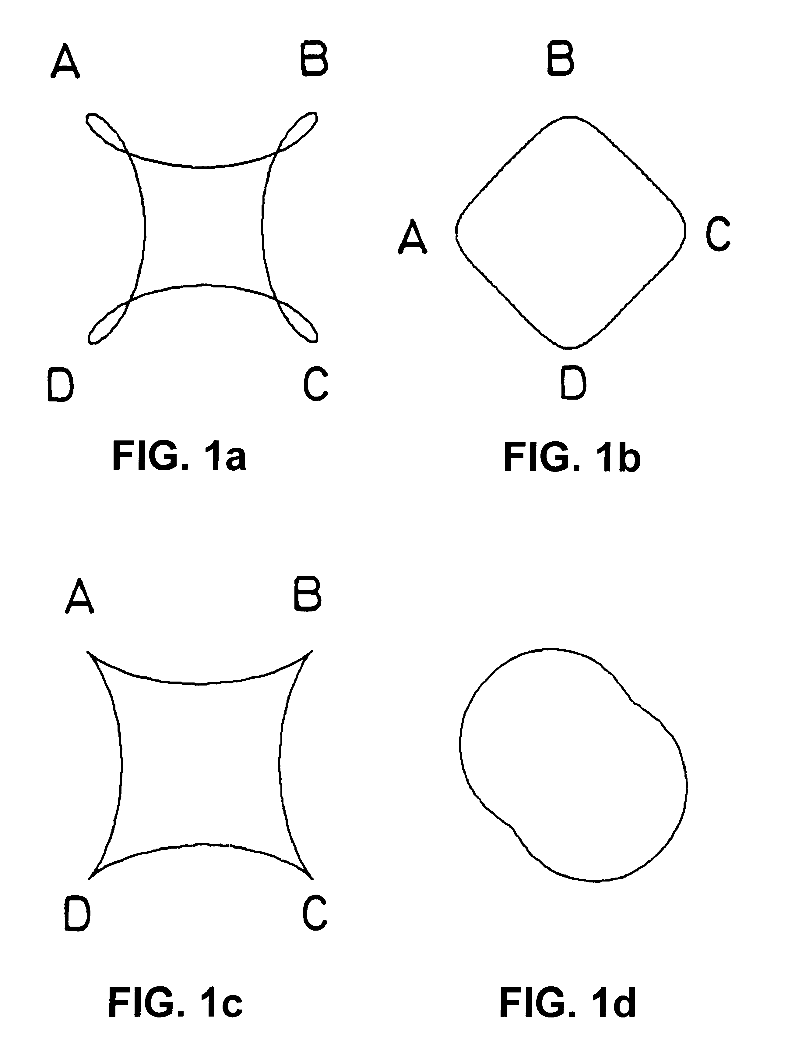
As explained in the Int. patent application WO99 / 26274 the present inventor has determined surprisingly that certain advantages can be obtained in a planar sputtering magnetron with a rectangular target when the motion of the magnet assembly is repetitive rather than non-repetitive. Non-repetitive, i.e. non-re-entrant motions are also known for the movement of magnet arrays of sputtering magnetrons. The motion of the magnet array may be complex, e.g. epitrochoidal, epicycl...


PUM

PropertyMeasurementUnit
widthaaaaaaaaaa
widthaaaaaaaaaa
lengthaaaaaaaaaa

Abstract

A magnetron including a target (2) for sputtering onto a substrate in described. The magnetron comprises a magnetic field generator (4) for generating a closed loop magnetic field adapted to generate a plasma race-track above the target (2) and a driving device for establishing relative substantially translational movement between the race-track and the target (2) and adapted to influence the magnetic field generated by the magnetic field generator (4) at least during part of the relative substantially translational movement, the distance between any point on the race track and the momentarily closest part of the one or more pieces (50) of ferromagnetic material varying in accordance with the relative substantially translational movement of the race-track and the target (2).

Description

The present invention relates to a magnetron with a magnet assembly suitable for sputtering or reactive sputtering of materials from a cathode target onto a substrate as well as a method of operating the magnetron.TECHNICAL BACKGROUNDThere have been many attempts to improve the erosion profile of sputtering magnetron targets and / or deposition uniformity onto a substrate by moving a magnet array relative to the target. For example, a rectangular planar magnetron with a moveable magnet assembly is known from U.S. Pat. No. 4,444,643 in which the magnetic assembly is translated laterally and parallel to the major axis of the target, DE-A-27 07 144 proposes a magnet assembly which is swept over a rectangular target along a linear path, U.S. Pat. No. 4,714,536 proposes that the magnet assembly is moved with a non-repetitive epicycloidal motion combined with a translational motion over the target, i.e. the magnet array performs a non-repetitive small epicycloidal motion distributed over th...

Claims


Application Information

Patent Timeline
Patent Type & Authority Patents(United States)
IPC IPC(8): H01J37/32H01J37/34B01J19/08C23C14/35
CPCH01J37/3408H01J37/3455
Inventor DE BOSSCHER, WILMERTVAN HOVE, STEVEN AUGUST
Owner BEKAERT ADVANCED COATINGS
Why Eureka
Try Eureka