High resolution flow imaging for ultrasound diagnosis

a flow imaging and ultrasound technology, applied in tomography, instruments, applications, etc., can solve the problems of reducing realtime performance, deteriorating range resolution, and difficulty in raising pressure any mor

Inactive Publication Date: 2002-07-16
TOSHIBA MEDICAL SYST CORP
View PDF4 Cites 65 Cited by
  • Summary
  • Abstract
  • Description
  • Claims
  • Application Information

AI Technical Summary

Problems solved by technology

However, in general, since the transmitted ultrasound pressure has a limitation that has been determined with consideration of safety for an object in the B mode, it is difficult to raise the pressure any more.
An excessively large burst wave number cause, however, range resolution to be deteriorated, thus an upper limit of the burst wave number being determined dependently on an allowed value of the range resolution.
If the number of frames for the B mode is ten frames per sec., the number for the CFM mode is six frames per sec., thereby reducing realtime performance.
However, this parallel simultaneous reception technique requires a transmitted beam to be spread, which reduces power transmitted to each sample position (depth position) in an object, ultimately lowering detection sensitivity.
Since the safety standard regulates the transmitted power not to exceed a given value, performing the parallel simultaneous reception generally reduces the detection sensitivity.
Therefore, the CFM mode, which is in charge of imaging signals of lower sensitivities, i.e., blood flow signals, has a limitation in using the parallel simultaneous reception technique.
The parallel simultaneous reception technique is still effective in improving realtime performance, but this technique is not a way that can always be used regardless of portions to be diagnosed.
Potential ability of the improved power mode has not been shown fully yet.
For example, the number of transmission burst waves still remains as conventional, thus lowering spatial resolution.
As a result, a thin blood vessel is displayed as being thick one or adjoining blood vessels are displayed without being separated, only having shown poor diagnosis performance.
The blooming, when it occurs, extremely deteriorates the spatial resolution, thus practical diagnosis being almost impossible.
This filtering processing causes the waveform of the received pulse to dull, thus making it further spread in the time-axis direction.
As a result, most of the roots of a received pulse that has spread in the time-axis direction exceed the noise level, thus causing the blooming.
Since the conventional apparatus is obliged to observe blood flows of fine blood vessels in the CFM mode, a shortage of the number of frames becomes fatal.
It is clear that a few frames in the CFM mode are still short for observation, and there is a fear that they fail to instantaneously detect a flowing blood.
Signals over 40 dB in sensitivity are all visualized with saturation at 40 dB, which results in poor gradation, thus providing only a blood flow image that gives a flat feeling in gradation.
There is also a fear of degrading diagnosis capability on account of such poor gradation.
Further, when diagnosing through observing the luminance levels of a blood flow image, the saturated portions cannot provide precise information about luminance levels.
In this way, where a blood flow is observed with the conventional apparatus with an objects into which the contrast agent is injected, there are various problems or drawbacks described above, thereby leading to a lowered performance in diagnosis, providing no practical use.
But these countermeasures have been taken at the sacrifice of spatial resolution.
Nevertheless, the power mode still succeeds a drawback that the resolution is low, like the conventional CFM mode.
Although such a demand has existed, a measure against the problem has not been proposed yet.
However, an amount that can be detected using the cross correlation method is a blood flow velocity having poor sensitivity.
This apparatus, however, not only uses an ultrasound pulse whose wave-continuous length is short, which is called short pulse, but also uses the cross correlation method, with color mapping of blood flow velocities inferior in sensitivity performed.
Because these techniques focus on obtaining velocities of objects in motion such as blood flow, there is a difficulty in sensitivity for detecting blood that flows at slower speeds or fine blood flows.
Therefore, a recent demand for ultrasound diagnosis that the existence itself of such blood flow is desired to be observed and confirmed at a higher accuracy has not been met yet.
(2) Although enhancement effects of a contrast agent can greatly raise detection sensitivity, the spatial resolution of blood flow images is deadly deteriorated, making diagnosis difficult.
(3) When an object to be observed is flow of fine blood vessels, there is a possibility that an observer fails to see significant behaviors of blood flows on account of the shortage of realtime performance. In such a case, diagnostic capability decreases extremely, lowering reliability in diagnosis.
(4) When enhancement effects of a contrast agent increases a detection sensitivity of blood flow up to a level as high as the B mode, the dynamic range for display in the power mode belonging to the CFM mode might become short. In such a case, display gradation in a blood flow image is saturated, lowering reliability in display. Additionally there is a fear that information on luminance lacks, lessening diagnostic capability.

Method used


Image

  • High resolution flow imaging for ultrasound diagnosis
  • High resolution flow imaging for ultrasound diagnosis
  • High resolution flow imaging for ultrasound diagnosis

Examples


first embodiment

(1) First Embodiment

Referring to FIGS. 1 to 4 and 39, a diagnostic ultrasound apparatus according to a first embodiment will now be described.

This diagnostic ultrasound apparatus is used to obtain a blood flow image by performing an contrast echo technique that requires a contrast agent to be injected to, for example, the vein of a patient, but it is not necessarily required that the contrast agent be injected. That is, the apparatus is also used in performing a non-contrast echo technique.

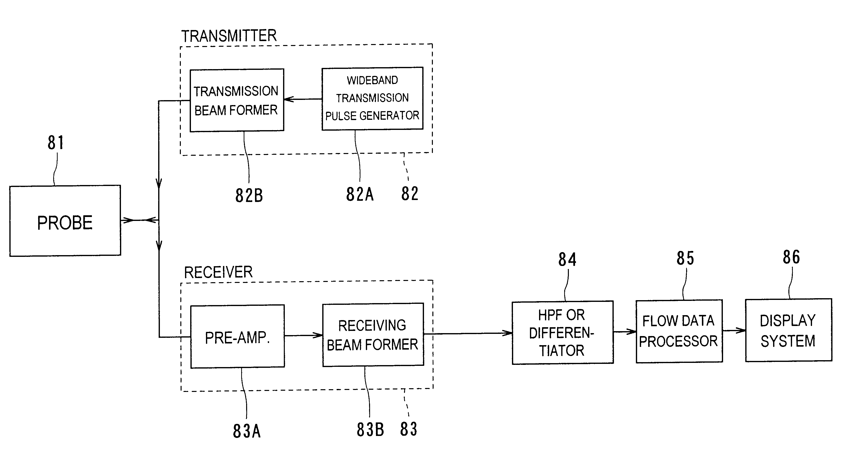
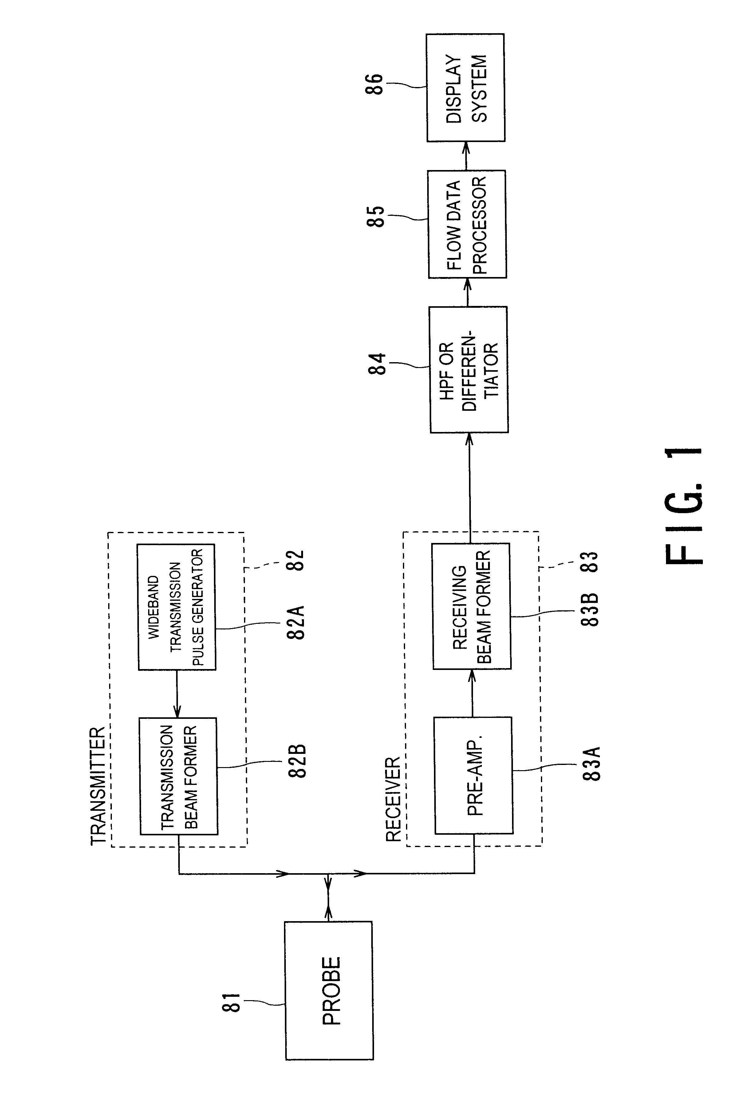
FIG. 1 is a block diagram that shows an outlined configuration of this diagnostic ultrasound apparatus. In this apparatus, a transmitter 82 and a receiver 83 are both connected with a probe 81. A highpass filter (HPF) or differentiator 84, flow data processor 85 and display system 86 are arranged in this order at the output side of the receiver 83. Either one of the HPF or the differentiator 84 is used to remove a signal component originated from surrounding tissue to extract a reflected signal fr...

second embodiment

(2) Second Embodiment

Referring to FIG. 5, a diagnostic ultrasound apparatus according to a second embodiment will now be described. This apparatus is used on the contrast echo or non-contrast echo method and uses a band-variable filter.

As shown in FIG. 5, between the receiving beam former 83B and the HPF or differentiator 84, a band-variables filer 87 functioning as filter means is inserted. The band-variable filter 87 has a passing band controlled by a frequency band setting device 88.

The band-variable filter 87 has a desired passing characteristic set to a passing echo signal at each depth in a raster along which a received beam is formed. This configuration is able to remove noise existing in an outside band of a signal so as to increase an S / N. In addition, echo signals are obtained, from which influences of both signal attenuation and band changes in the depth direction are corrected. Further it is possible that the fundamental wave of high sensitivity, a harmonic wave of less ...

third embodiment

(3) Third Embodiment

Referring to FIG. 6, a diagnostic ultrasound apparatus according to a third embodiment will now be described. This apparatus is concerned with the changeover of transmission / reception characteristics in cases where the contrast and non-contrast echo methods are selectively used.

As shown in FIG. 6, on top of the configurations in FIG. 5, there are additionally provided an echo-method changeover switch 91, transmission-number setting device 92, and direction-number setting device 93.

The echo-method changeover switch 91 is provided to, for example, manually command the changeover between the contrast and non-contrast echo methods. The switch signal is given both the direction-number setting device 93 and the transmission-number setting device 92.

The direction-number setting device 93 is placed to set the number of directions for parallel simultaneous reception and its setting signal is sent to both the transmitter 82 and the receiver 83. The transmission-number sett...


PUM


Abstract

In a high-resolution flow mode, a diagnostic ultrasound apparatus and a diagnostic ultrasound method that provide an image of blood flow or perfusion is provided with higher sensitivity and high resolution, which makes it possible to precisely observe the presence of fine blood vessels. In this apparatus, by scanning means (81 to 83), with a ultrasound pulse having a wideband frequency characteristic transmitting at least two times in the same direction within an object, a cross section to be imaged therein is scanned to obtain an echo signal at each time of transmission. By processing means 84, highpass filtering or differential processing is performed with rows of data in the time axis direction of an echo signal acquired at each sample location in the cross section, so that signals from blood flow are extracted. By producing means 85, the processed signals are produced into data of luminance or power. This data is displayed by displaying means 86 as a high-resolution color (flow) image or grayscale flow image indicative of blood flow or perfusion.

Description

1. Field of the InventionThe present invention relates to a diagnostic ultrasound apparatus and a method of diagnosis with ultrasound images capable of visualizing images of blood flow as an element in motion in an object to be imaged at a higher degree of resolution and high sensitivity, and in particular, to the apparatus and method preferable to an contrast echo technique performed with an ultrasound contrast agent injected into an object for acquiring blood flow images.2. Description of the Related ArtA diagnostic ultrasound apparatus has a wide variety of advantages, such as, relatively compact in size, lower price, no X-ray exposure, and availability of blood flow imaging on an ultrasound Doppler technique, thereby providing an indispensable today's imaging modality in the field of clinics.Particularly, the blood flow imaging on the ultrasound Doppler technique, which functions strongly in finding lesions in the cardiac system and others, is called color flow mapping (CFM) or ...

Claims


Application Information

Patent Timeline
Patent Type & Authority Patents(United States)
IPC IPC(8): A61B8/00A61B8/06G01S7/52G01S15/89
CPCA61B8/06A61B8/13A61B8/481G01S7/52039G01S7/52071G01S15/8979
Inventor SHIKI, EIICHIMINE, YOSHITAKA
Owner TOSHIBA MEDICAL SYST CORP
Why Eureka
Try Eureka