Method for removing reactive metal from a reactor system

a reactor system and reactive metal technology, applied in metal/metal-oxide/metal-hydroxide catalysts, chemical/physical processes, etc., can solve the problems of not teaching the desirability nor the need for removing metal from the reactor system, and the catalyst activity is reduced unexpectedly and undesired, so as to improve the reproducibility of catalytic operations and reduce catalyst contamination

Inactive Publication Date: 2002-07-16
CHEVRON PHILLIPS CHEMICAL CO LP
View PDF264 Cites 35 Cited by
  • Summary
  • Abstract
  • Description
  • Claims
  • Application Information

AI Technical Summary

Benefits of technology

is to reduce catalyst contamination from a freshly metal-coated reactor system which would otherwise result in catalyst deactivation. This new process will also improve the reproducibility of catalytic operations, since catalyst activity and life can be better predicted.
Indeed, the art teaches the advantages of combining one of the preferred coating metals--tin--with a reforming catalyst, specifically with a platinum L-zeolite catalyst. U.S. Pat. No. 5,279,998 to Mulaskey et al., teaches that activity and fouling rate improvements are associated with treating the exterior of the platinum L-zeolite catalyst with metallic tin particles having an average particle size of between 1 and 5 microns (tin dust). For example, Table I of the Mulaskey patent shows improved catalyst performance when metallic tin dust is combined with a platinum L-zeolite catalyst that has been treated with fluoride according to the process of U.S. Pat. No. 4,681,865.
We have discovered that there are problems associated with using metal-coated reactor systems--especially freshly-coated systems--in the presence of certain catalysts, and we have discovered the cause of and solutions for these problems. Thus, one object of the present invention is to reduce catalyst contamination from a freshly metal-coated reactor system. Another object of the invention is to ensure that catalyst contamination is avoided, for example when replacing a conventional catalyst with a halided catalyst.
In yet another embodiment, the invention is a method for reducing catalyst contamination from a metal which was used to coat a reactor system. The method comprises contacting a metal-coated reactor system prior to catalyst loading with a getter, preferably a gaseous halogen-containing compound, to produce movable metal; and removing and fixating at least a portion of the movable metal from the reactor system. The conversion catalyst is then loaded into the reactor system, and conversion operations begin with feed being converted to product in the reactor system. This method is preferably applied to a freshly-coated reactor system.

Problems solved by technology

Recent attempts to utilize this second generation of catalysts for ultra-low sulfur reforming resulted in an unexpected and undesired reduction in catalyst activity.
None of these patents or patent applications disclose any problems associated with the metal-coated reactor systems.
They neither teach the desirability nor the need for removing metal from the reactor system, especially not prior to catalyst loading or prior to hydrocarbon processing.
We have discovered that there are problems associated with using metal-coated reactor systems--especially freshly-coated systems--in the presence of certain catalysts, and we have discovered the cause of and solutions for these problems.
Moreover, the art has not appreciated the need or desire to remove this reactive metal prior to catalyst loading, especially prior to loading halided catalysts.
We have found that tin-coated reactor systems, especially those with freshly prepared tin intermetallics, can lose tin from the tin-coated surfaces when contacted with halogen-containing gases, for example, during the start-up of a reforming process using a halided Pt L-zeolite catalyst which evolves acid halides, including HCl.
This metal loss results in tin depositing on the catalyst and reduced catalyst activity.

Method used


Image

  • Method for removing reactive metal from a reactor system
  • Method for removing reactive metal from a reactor system
  • Method for removing reactive metal from a reactor system

Examples


example 1a

Stanniding Steel Using a Tin Paint

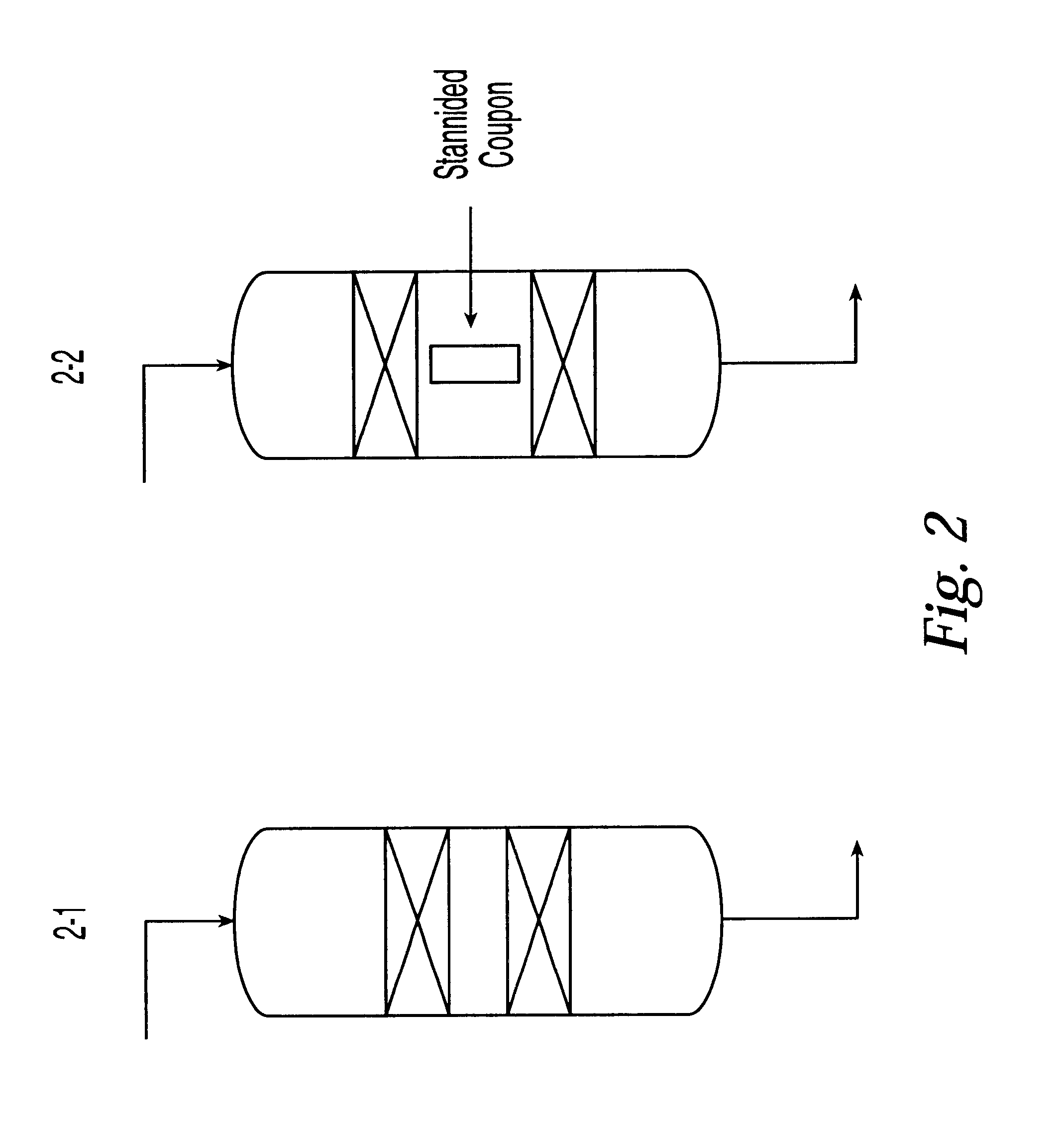
Coupons of type 321 type or type 347 stainless steel were coated with a tin-containing paint. The paint consisted of a mixture of 2 parts powdered tin oxide, 2 parts finely powdered tin (1-5 microns), 1 part stannous neodecanoate in neodecanioc acid (20% Tin Tem-Cem manufactured by Mooney Chemical Inc., Cleveland, Ohio which contained 20% tin as stannous neodecanoate) mixed with isopropanol, as described in WO 92 / 15653. The coating was applied to the steel surface by painting and letting the paint dry in air. After drying, the painted steel was contacted with flowing hydrogen at 1100.degree. F. for 40 hr to produce a stannided steel surface comprising intermetallics including iron stannides.

Some experiments were done in a pilot plant having 1 / 4" OD reactor tube made of 316 stainless steel. The reactor tube was coated with the tin-containing paint described above. The coating was applied to the inner surface of the pilot plant by filling the reactor ...

example 1b

Analysis of Stannided Steel

The resulting tin coated steels with their intermetallic tin layers were examined visually for completeness of coating. Samples were mounted in a clear epoxy resin and then ground and polished in preparation for analysis with the petrographic and scanning electron microscopes (SEM). EDX analysis can be used to determine the chemical composition of the layers. The cross-sections of the materials showed that the tin paint had reduced to metallic tin under these conditions and formed a continuous and adherent metallic (iron / nickel stannide) protective layer on the steel surface. Nickel- and iron-containing stannides were present at a thickness of between about 2 to 5 microns. A nickel depleted underlayer (2-5 microns thick) was also present. On the surface, microscopic tin balls and globules were observed.

example 2

Preparing a Halided Platinum L-zeolite Catalyst

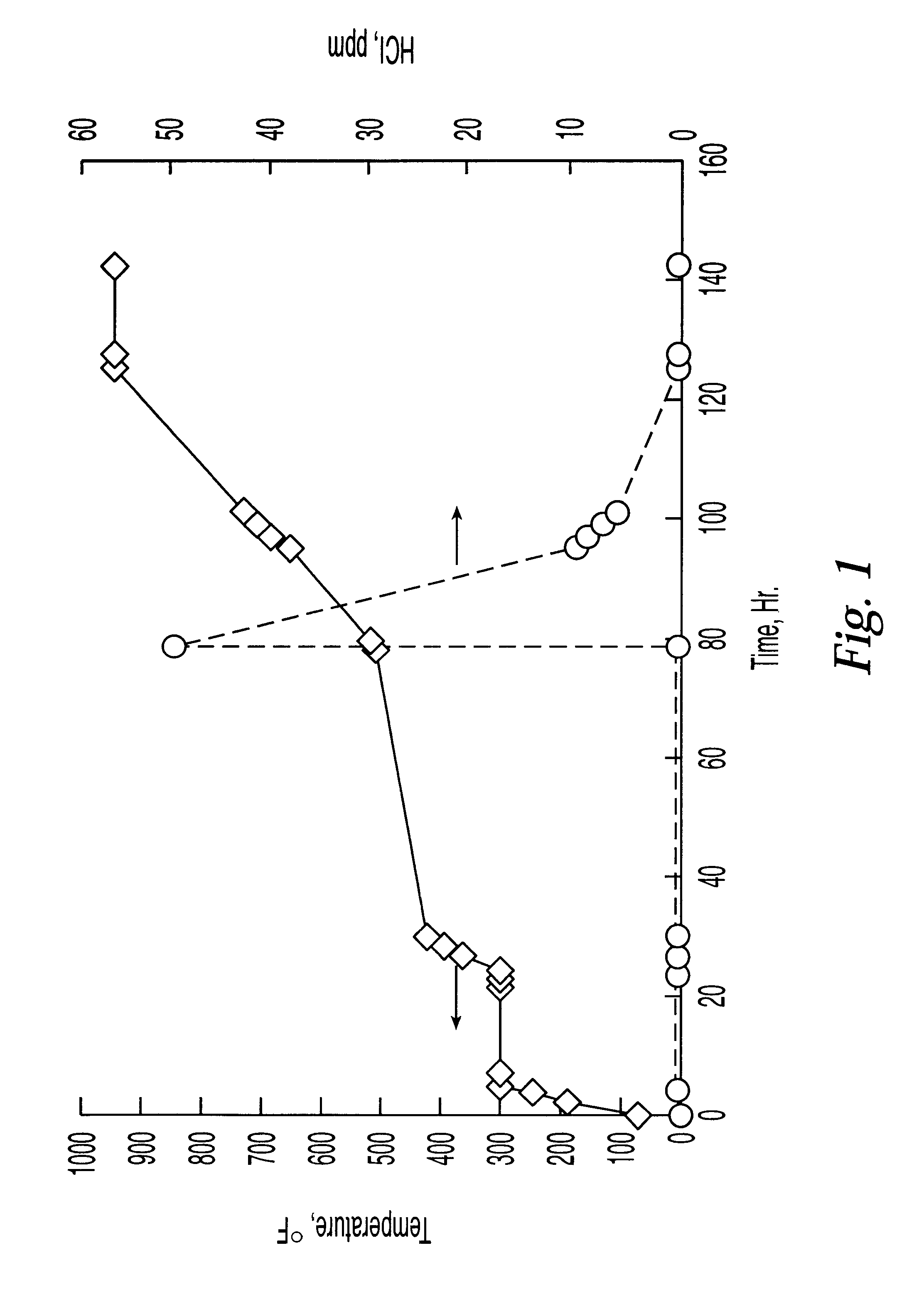
A halided platinum L-zeolite catalyst was prepared in a manner similar to EP 498,182A1, Example 4. Experiments showed that this catalyst evolved HCl and HF when heated to 500.degree. F. in the presence of hydrogen. FIG. 1 shows HCl evolution as a function of temperature. HF loss is also observed. Gastec tubes were used to measure HCl concentration. Gas rates were 1300 GHSV, once-through. Hydrogen was added at time=79 hours. This catalyst was used for all the activity tests described below and as a source HCl and HF in some of the following examples.


PUM

PropertyMeasurementUnit
particle sizeaaaaaaaaaa
temperaturesaaaaaaaaaa

Abstract

A method of removing reactive metal from a metal-coated reactor system, comprising contacting at least a portion of a metal-coated reactor system containing reactive metal with a getter to produce movable metal, and fixating the movable metal, the getter, or both. The contacting is preferably done prior to catalyst loading. A preferred coating metal comprises tin and a preferred getter comprises HCl. The invention is also a method for reducing catalyst contamination from a metal which was used to coat a reactor system. The method comprises contacting a metal-coated reactor system, with a gaseous halogen-containing compound to produce movable metal; thereafter or simultaneously, at least a portion of the movable metal is removed from the reactor system. Then a halided catalyst is loaded into the reactor system.

Description

The invention is a method of removing reactive metal from at least a portion of a metal-coated hydrocarbon conversion reactor system, so that the reactive metal does not deactivate the hydrocarbon conversion catalyst. It is especially applicable to catalytic reforming processes using halided catalysts.BACKGROUND AND RELEVANT REFERENCESPlatinum L-zeolite catalysts for low-sulfur reforming were invented in the early 1980's. After about 10 years of intensive effort, and much research, low sulfur reforming was commercialized in the early 1990's. Progress toward commercialization required many discoveries. Two key discoveries were the criticality of ultra-low sulfur levels in the feed, and the impact of these ultra-low sulfur levels on reactor metallurgy, i.e., the discovery of the need to prevent coking, carburization and metal dusting. A preferred way to prevent coking, carburization and metal dusting utilizes a metal protective layer, especially one comprising tin.While commercializat...

Claims


Application Information

Patent Timeline
Patent Type & Authority Patents(United States)
IPC IPC(8): B01J8/00B01J23/92B01J23/90B01J19/02B01J19/00B01J38/00B01J38/42C23F1/12C10G35/085C10G35/04C23F1/10C10G35/00C22B11/02C10G35/095C22B11/00B01J33/00B01J29/62
CPCB01J8/008B01J19/0026B01J19/02B01J23/92B01J29/62B01J38/42C10G35/04C10G35/085C10G35/095C22B11/025C23F1/12B01J2219/00247B01J2219/0236B01J2219/024C10G2400/30Y10S502/516Y02P10/20
Inventor HOLTERMANN, DENNIS L.CHEN, HONG CHIUWOLPERT, RICHARD MWILSON, CHARLES R.HAGEWIESCHE, DANIEL P.
Owner CHEVRON PHILLIPS CHEMICAL CO LP
Why Eureka
Try Eureka