Pressurized seal for submersible pumps

a submersible pump and pressurized seal technology, applied in the direction of pump, positive displacement liquid engine, liquid fuel engine, etc., can solve the problems of no predictability as to the failure of the seal, electrical shortening of the motor, and the seal runs against the sha

Inactive Publication Date: 2002-07-23
SHELL OIL CO
View PDF2 Cites 71 Cited by
  • Summary
  • Abstract
  • Description
  • Claims
  • Application Information

AI Technical Summary

Problems solved by technology

The lip seals run against the shaft and, over time, will fail.
Mechanical seals are the norm in the industrial pump industry as they are generally long lasting, but there is no predictability as to their failure.
This is generally not a major problem with a non-submersible pump, but with a submersible pump the pumpage often gets into the motor resulting in electrically shorting out the motor.
Prior art submersible motors generally are not designed to withstand internally generated pressure caused by motor winding temperature increase and / or the temperature rise due to the temperature of the pumpage in the sump / storage tank.
The motor is shorted out and will fail on the next start
With this pre-alarm, maintenance is limited to a recharge of the oil system, vs. a complete tear-down of the pump which is ultimately required when water gets into the pump oil chamber.

Method used


Image

  • Pressurized seal for submersible pumps
  • Pressurized seal for submersible pumps
  • Pressurized seal for submersible pumps

Examples


Embodiment Construction

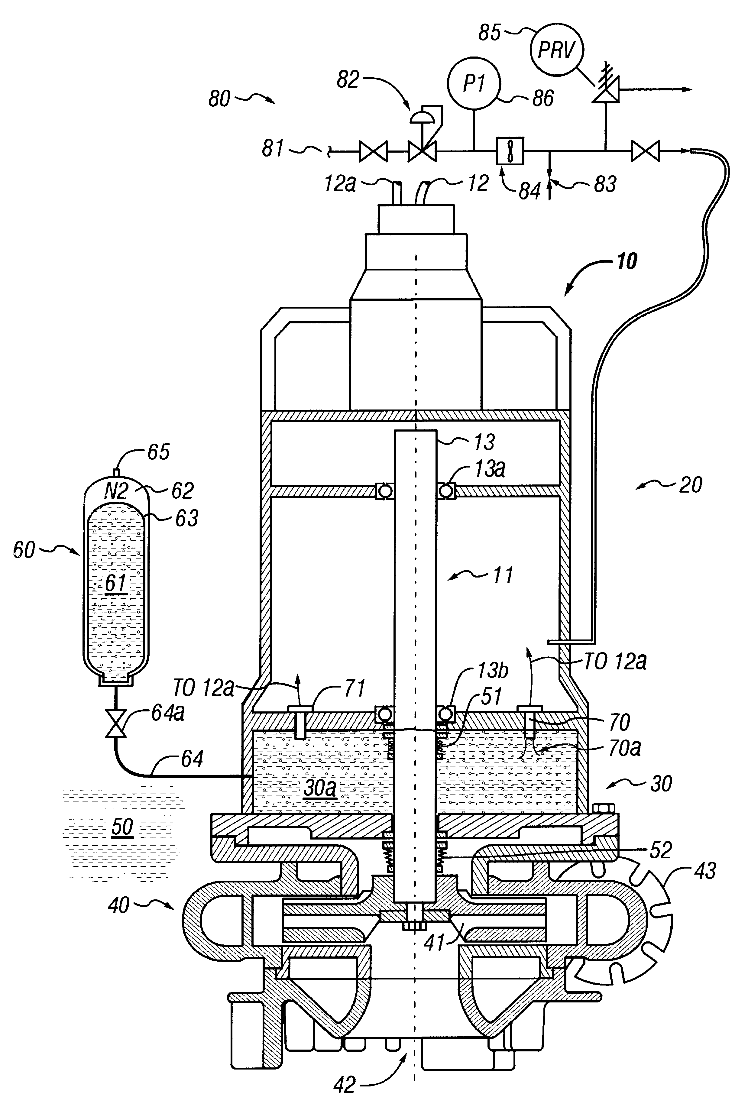
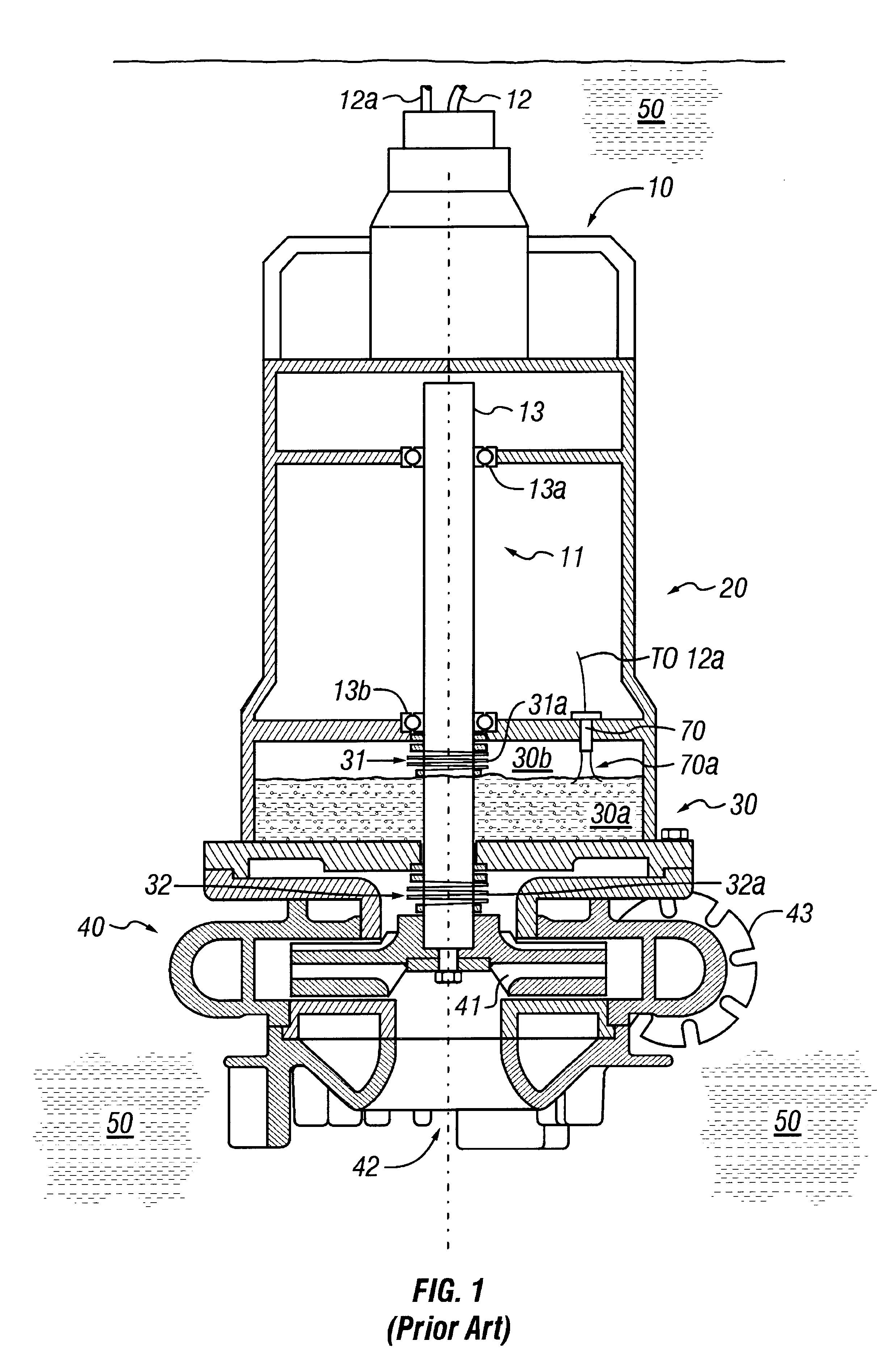
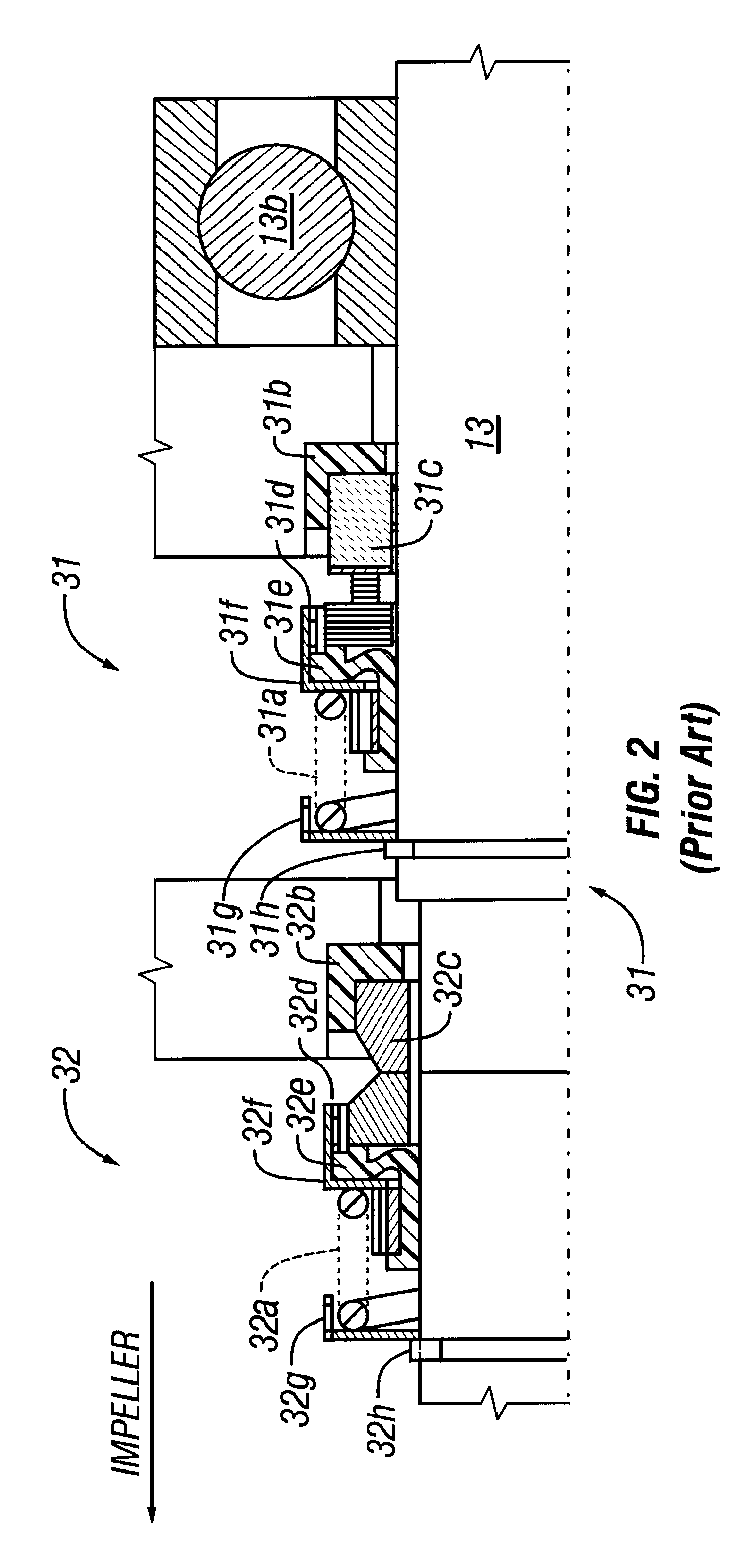
Referring now to FIG. 1, a prior art submersible pump 10 is shown submerged in a fluid 50 (hereinafter referred to as "pumpage" or "pumpage fluid") confined within a sump or storage tank (not shown). The pump 10 comprises a motor section 20, a sealed, partially filled oil reservoir 30 and a pump section 40. The sealed oil reservoir 30 comprises a portion that is partially filled with oil 30a and a non-pressurized portion 30b above the oil level 30a. The motor 11 receives power by means of electrical power cables 12 and drives a motor shaft 13. The motor shaft 13 sealingly extends through the oil reservoir 30 and into the pump section 40 where it is rigidly connected to an impeller 41 so as to cause rotation thereof when motor shaft 13 rotates. The pump section 40 is provided with an inlet (or suction) port 42 for drawing pumpage fluid 50 into the pump in the usual manner, and a discharge port 43 for discharging pumpage fluid 50 from the sump / storage tank and to another location, e.g...


PUM


Abstract

A submersible pump employs a sealed, oil-filled chamber with a moisture-sensing probe to detect the presence of any pumpage, such as water, which has leaked into the chamber. If contamination is detected, the pump may be shut down for repairs before it fails. Two mechanical seals are installed the lower seal is located between the pump and the oil chamber and an upper seal is located between the oil chamber and the motor. The improvement disclosed herein combines a pressurized oil accumulator with the pump oil chamber described above. The accumulator is divided into two compartments separated by a bladder, one compartment being connected to the reservoir of the pump and filled with oil for providing make-up oil to the reservoir and for accepting surplus (expansion) oil from the reservoir. The second compartment is pressurized and applies pressure to the bladder that, in turn, transfers the pressure to the oil in the first compartment and to the oil-filled chamber. The purpose is to pressurize the pump oil chamber in order to equalize pressure across the seals and thereby prevent failure of the seals or, at least, extend their life. The invention also includes apparatus for purging the motor casing with air and a pressure transducer for detecting a decrease in reservoir oil pressure.

Description

1. Field of the InventionThe invention is directed to submersible centrifugal pumps and to methods and apparatus for providing pressurized sealing of the motors thereby improving their operational life. The invention is particularly applicable and directed to coker maze pumps used in delayed coker processes to recirculate the water from coker maze pits containing coke fines suspended in water, also known as coke-laden fines. The invention may also have application in other submersible pump services, such as water lift stations and sewage treatment plants.2. Description of Related ArtPrior art submersible pumps employ a sealed, partially oil-filled chamber having a moisture-sensing probe extending into the oil to detect the presence of any pumpage, which may be water or water containing suspended coker fines. If contamination is detected, steps may be taken to protect the motor. Two seals are utilized on the motor shaft, a lower seal located between the pump and the oil chamber (pump...

Claims


Application Information

Patent Timeline
Patent Type & Authority Patents(United States)
IPC IPC(8): F04D15/02F04D13/08F04D13/06
CPCF04D13/083F04D15/0263F04D29/128
Inventor HOLMES, JEFFREY WAYNE
Owner SHELL OIL CO
Why Eureka
Try Eureka