Optical fiber amplifier for clamping and equalizing gain in optical communication system

a technology of optical communication system and optical fiber amplifier, which is applied in the direction of lasers, transmission, electromagnetic transmission, etc., can solve the problems of inability to apply the prior art clamping gain of the optical fiber amplifier shown in fig. 1 to the wdm system, inability to produce sufficient output power, and increase transmission errors. , to achieve the effect of high output power

Inactive Publication Date: 2002-07-23
SAMSUNG DISPLAY CO LTD
View PDF7 Cites 12 Cited by
  • Summary
  • Abstract
  • Description
  • Claims
  • Application Information

AI Technical Summary

Benefits of technology

Another object of the present invention is to provide an optical fiber amplifier for clamping and equalizing gain, which can supply a high...

Problems solved by technology

As a result, transmission errors can increase due to the above mentioned gain variations.
In this case, the sufficient output power cannot be produced with existing configurations of gain-clamped optical fiber amplifier.
Eventually, the optical fiber amplifier for clamping gain of the prior art shown in FIG. 1 cannot be applied to the WDM system because the equalization of gain is not considered.
However, in the case of the optical fiber amplifier including a gain-equalizing filter, there is a problem of the relatively large loss for the output of the signal since the filter is located at the output terminals.
However, there is the same problem as in the case of FIG. 1.
That is, a high output power is difficult to obtain as the fourth optical coupler 14 is provided at the output terminal and act...

Method used


Image

  • Optical fiber amplifier for clamping and equalizing gain in optical communication system
  • Optical fiber amplifier for clamping and equalizing gain in optical communication system
  • Optical fiber amplifier for clamping and equalizing gain in optical communication system

Examples


Embodiment Construction

The present invention will be described in more detail with reference to the preferred embodiment shown in the attached drawings.

As described above, channels are growing in number to increase transmission capacity, and a wide gain band of more than 30 nm has already been used in long distance transmission systems, but optical fiber amplifiers for use in WDM network systems have not been developed yet satisfactorily for the case of channel variations in the input signal.

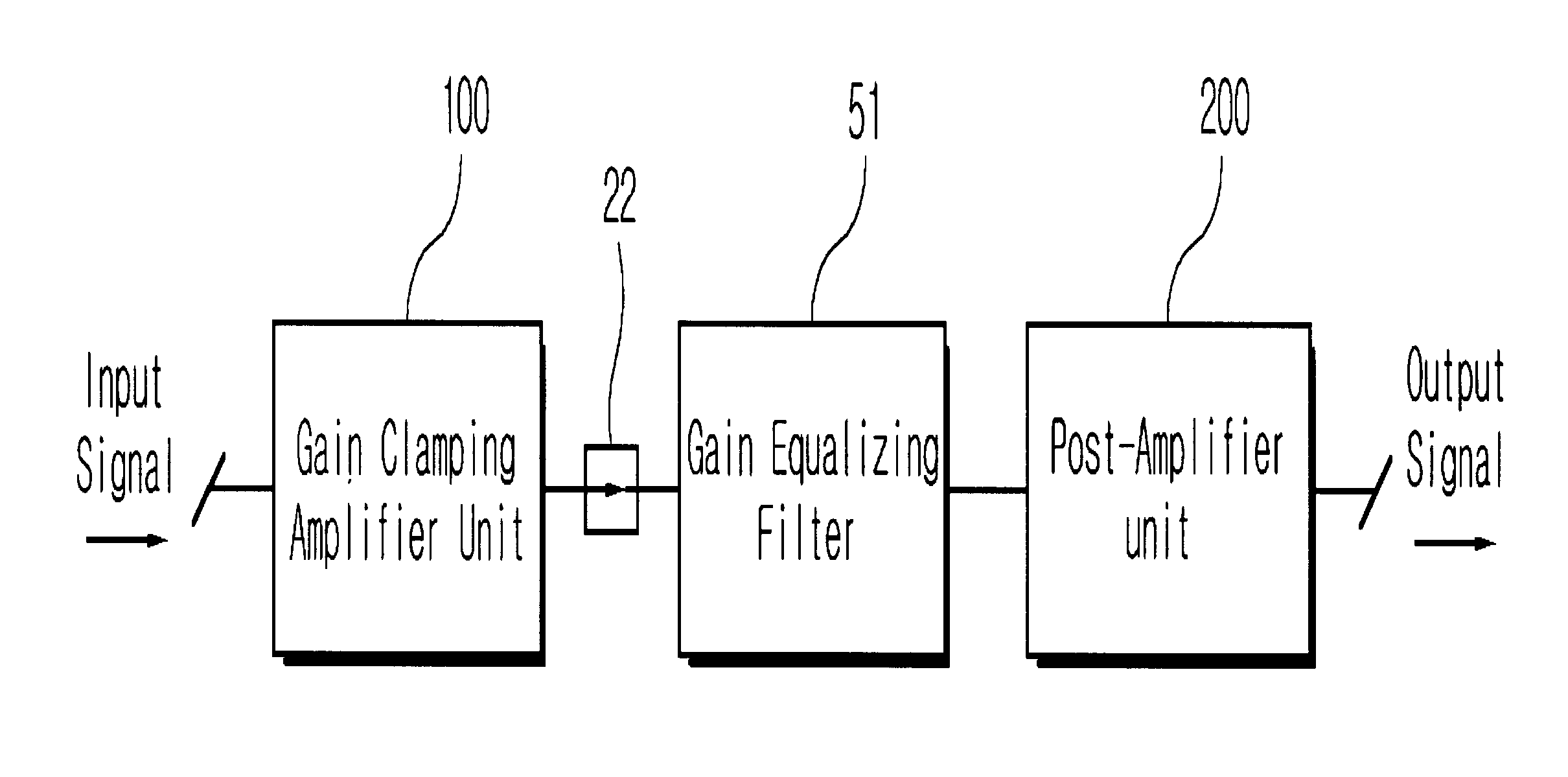
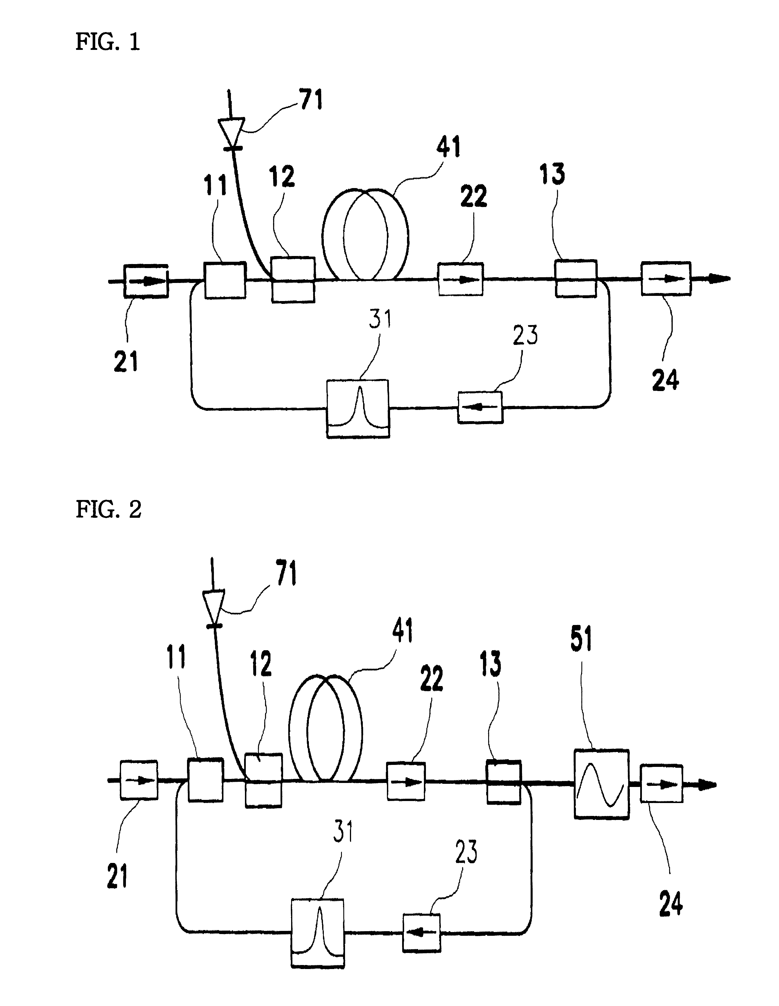
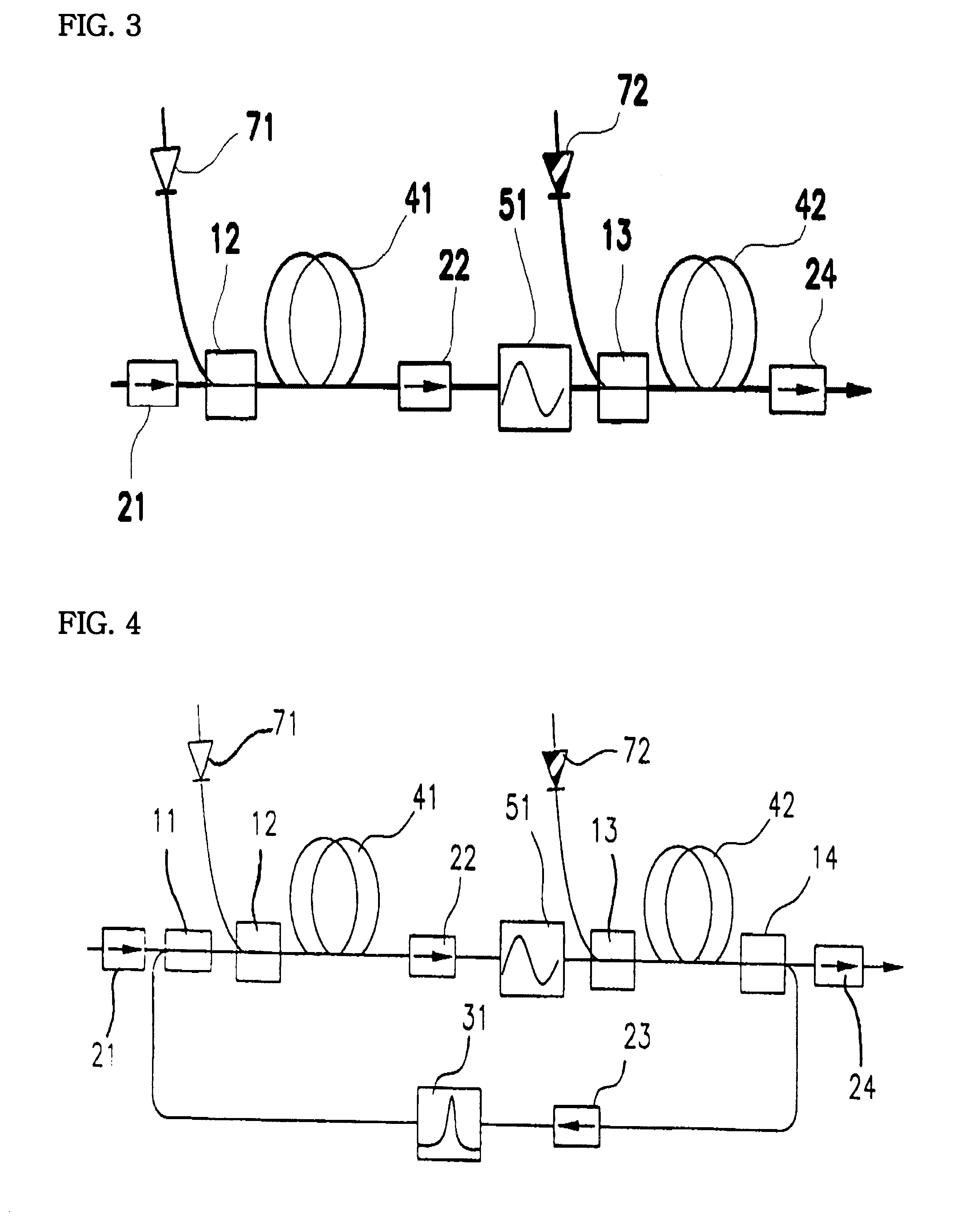
FIG. 5 is a block diagram showing an optical fiber amplifier for clamping and equalizing gain in optical communication system of the present invention, and FIG. 6 is a detailed diagram of an example of the amplifier of FIG. 5.

The present invention is mainly made up of a gain clamping amplifier unit 100, a gain equalizing filter 51, and a post-amplifier unit 200.

The gain clamping amplifier unit 100 includes a first optical coupler 11 for coupling input optical signals, a first amplifying medium 41 for amplifying and ou...


PUM


Abstract

The present invention is to provide an optical fiber amplifier for clamping and equalizing gain in optical communication systems comprising: a gain clamping amplifier unit for clamping the gain, so as to make input signals have the same output power for each channel by applying a compensating signal; a second isolator for passing the input signal light from said gain clamping amplifier unit and isolating the light coming from the opposite direction; a gain equalizing filter for equalizing the output gain spectrum from the input signal from said second isolator; and a post-amplifier unit for amplifying the signal from said gain equalizing filter. Thus, the optical fiber amplifier is capable of clamping gain automatically by maintaining the same population inversion, and capable of maintaining the same gain equalization for the wide signal gain band to achieve the high transmission capacity, in cases that the number of channel varies in the input signal, while providing a high output signal power.

Description

The present invention relates to an optical fiber amplifier for clamping and equalizing gain in optical communication systems, and particularly to an optical fiber amplifier for clamping and equalizing gain, capable of clamping gain automatically by maintaining the same population inversion, and capable of maintaining the same gain equalization for the wide signal gain band to achieve the high transmission capacity, in the case that the number of channel varies in the input signal.Generally, in optical communication systems, an optical amplifier is used to compensate loss in a signal. Such an optical amplifier is a device for compensating loss of attenuation of the optical signal due to a long distance transmission.Optical fiber amplifiers are widely used in optical communication systems. Especially, an erbium doped fiber amplifier (EDFA) is used to amplify a signal periodically in certain distance so as to compensate the attenuation of optical signal caused by the long distance tra...

Claims


Application Information

Patent Timeline
IPC IPC(8): H01S3/067H01S3/06H01S3/10
CPCH01S3/06754H01S3/10023H01S2301/04H01S3/1302
Inventor LEE, DONGHANCHOI, HYUNBEOM
Owner SAMSUNG DISPLAY CO LTD
Why Eureka
Try Eureka