Method for making a carbonated soft drink bottle with an internal web and hand-grip feature

a carbonated beverage bottle and web technology, applied in the field of one-piece carbonated beverage bottle blow molding machine and method, can solve the problems of bottle performance and appearance degradation, bottle containing approximately one liter of carbonated beverage product or more, and the conductor of heat energy of polypropylene used to blow mold the bottle is relatively poor

Inactive Publication Date: 2002-08-06
AMCOR RIGID PLASICS USA LLC
View PDF8 Cites 30 Cited by
  • Summary
  • Abstract
  • Description
  • Claims
  • Application Information

AI Technical Summary

Problems solved by technology

The polyester material used to blow mold the bottle is a relatively poor conductor of heat energy.
Because of its relatively large cross-sectional size, bottles containing approximately one liter of the carbonated beverage product or more are often difficult for a consumer to grip, particularly while pouring the beverage into a cup or glass.
However, inadequate heating of the web portion in the preform and inadequate cooling of the web portion in the blow molded bottle create crystalline structures, stresses, and web distortions that tend to degrade bottle performance and appearance.
Furthermore, the internal pressure created inside the bottle from the carbonated beverage act on structural stresses often causing the web portion to separate from the bottle sidewall portion.

Method used


Image

  • Method for making a carbonated soft drink bottle with an internal web and hand-grip feature
  • Method for making a carbonated soft drink bottle with an internal web and hand-grip feature
  • Method for making a carbonated soft drink bottle with an internal web and hand-grip feature

Examples


Embodiment Construction

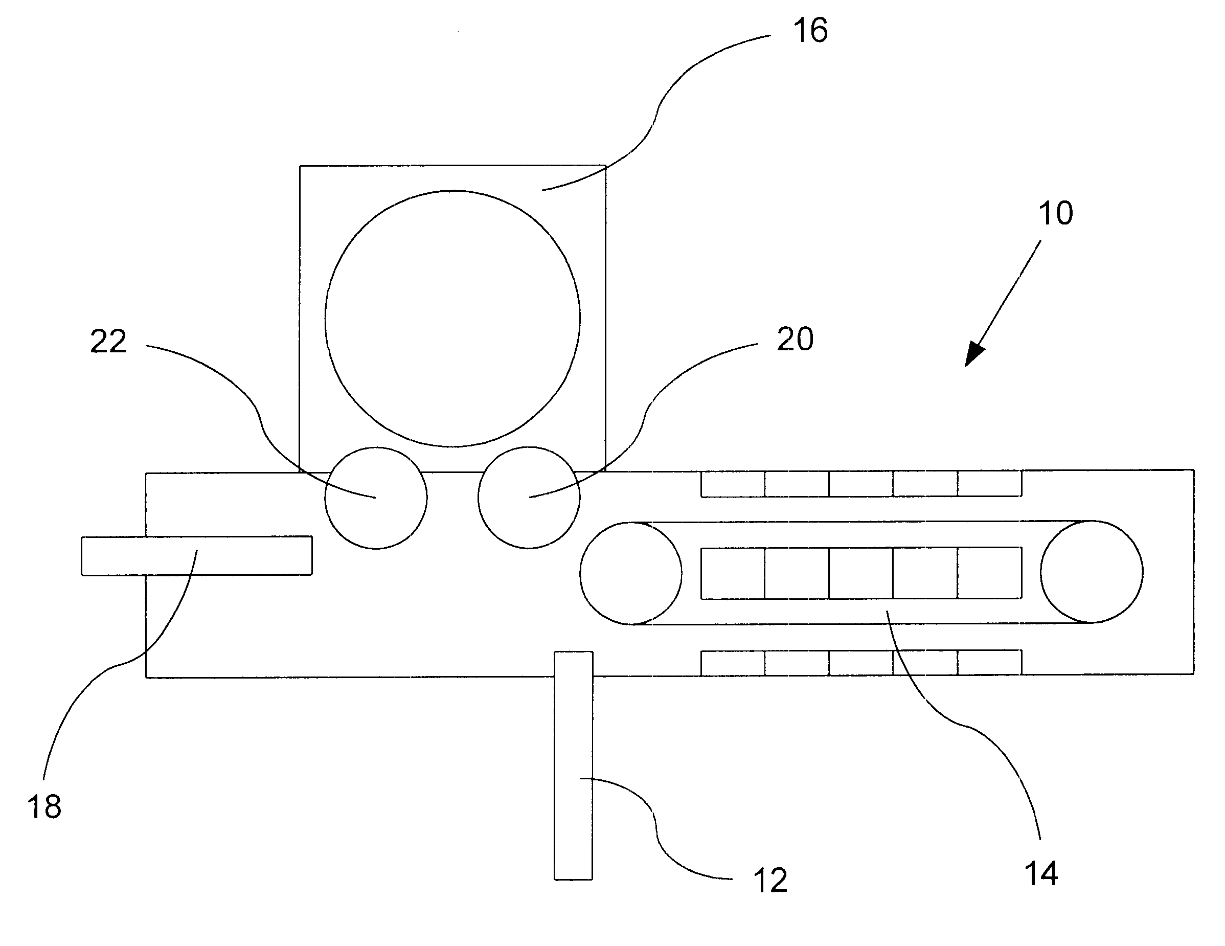
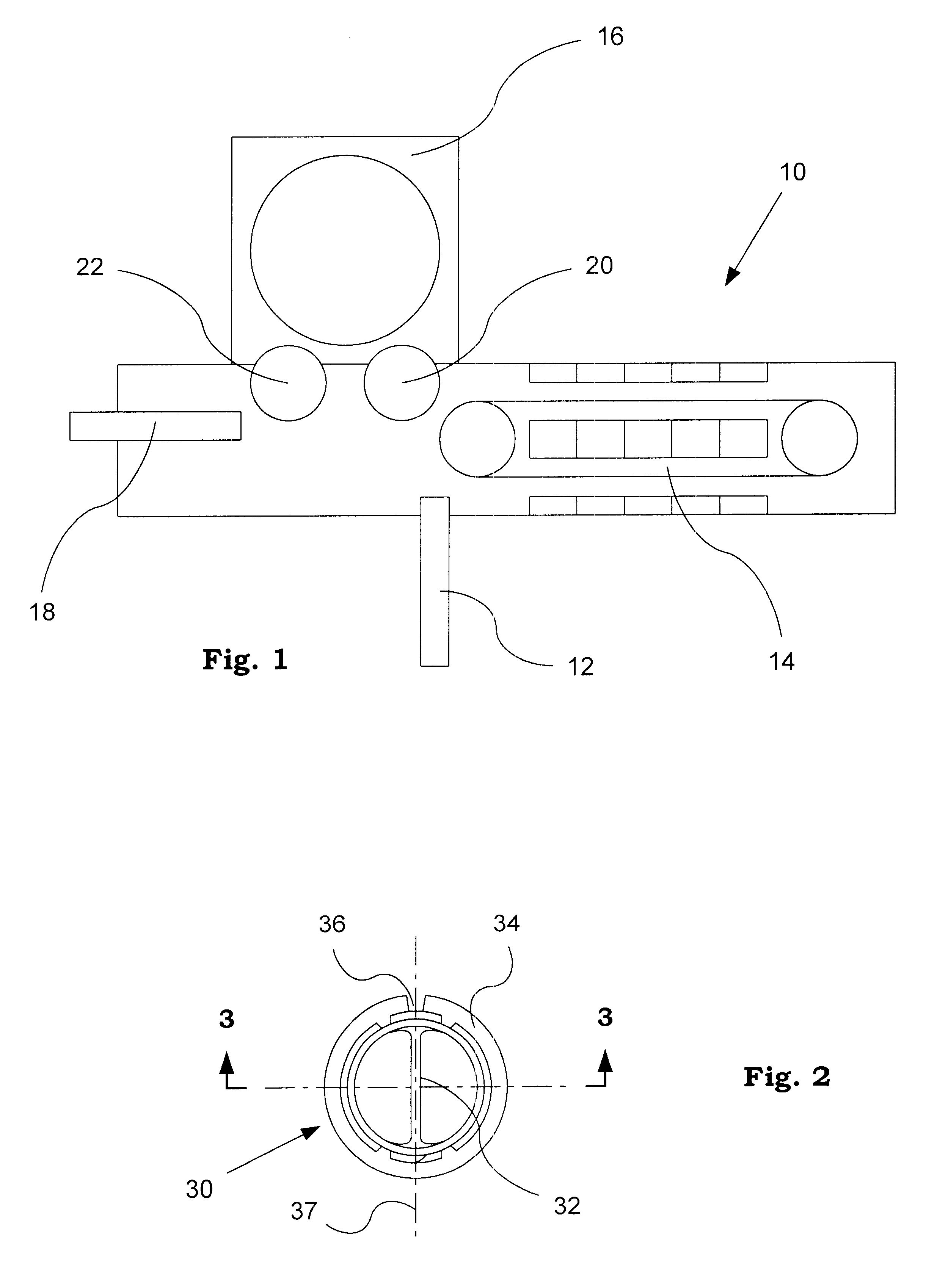
Referring now to the drawings, FIG. 1 illustrates in schematic plan view a blow-molding machine 10 for practicing the invention disclosed. Entering through a preform in-feed and alignment device 12, blow-molding machine 10 receives a preform 30 manufactured on a separate injection-molding machine. Such injection-molding machines are common in the industry, and it is not necessary to discuss fully these machines in this disclosure.

The blow-molding machine 10 consists of six main subsections: the preform in-feed and alignment device 12, an oven 14 where preform 30 receives a heat-treatment, preform transfer 20, blow molding section 16 where preform 30 is inflated and shaped into a bottle, bottle transfer 22, and bottle output 18. The blow-molding machine 10 further consists of, although not illustrated, all necessary operating controls, drives, actuators, valves, switches, relays, wiring, plumbing, blowers, ducting, utility connections and other related components common to blow moldi...


PUM

PropertyMeasurementUnit
pressureaaaaaaaaaa
temperatureaaaaaaaaaa

Abstract

A machine and method for blow molding a polyester bottle for carbonated beverages with an internal web structure positioned between two hand-grip depressions. The machine and method uses an injection-molded preform having a web feature and maintains the web of the preform in a precise position during heat-treatment and eventual blow molding into the bottle. Heat-treatment involves an oven capable of heating and cooling selected regions of the preform by using a combination of shields, heat energy reflective surfaces, and cooling airflows. Bottle blow molding involves precise placement of the preform relative to hand-grip surfaces in a blow mold cavity and cooling airflow of the internal web structure before bottle removal.

Description

1. Field of the InventionThis invention relates generally to a machine and method for blow molding a one-piece carbonated beverage bottle with an internal web structure positioned between two hand-grip depressions. Although not exclusively, a bottle blow molder will use a polyethylene terephthalate (PET) polyester material to make the bottle, a material having a molecular structure capable of biaxial orientation.2. Description of the Prior ArtCarbonated beverage products are commonly contained in polyester bottles. This bottle typically comprises: a neck portion defining an opening, a shoulder portion depending therefrom, a closed base portion, and a sidewall portion extending between the base and shoulder portions. The sidewall portion typically has a cross-sectional shape circular in character.The method for making polyester bottles by biaxially orienting its material structure is well known. The method requires a preform made first, usually with an injection molding process. This...

Claims


Application Information

Patent Timeline
Patent Type & Authority Patents(United States)
IPC IPC(8): B29C49/68B29C49/64B29C49/12B29C49/00B29C49/08B29C35/08B29C49/66B29C49/06
CPCB29C49/0078B29C49/12B29C49/68B29B2911/1402B29B2911/14026B29B2911/14033B29B2911/1404B29B2911/14326B29B2911/14333B29B2911/1444B29B2911/14466B29C49/06B29C49/66B29C2035/0822B29K2067/00B29C2949/26B29C2949/28B29C2949/24B29C2949/22B29C2949/0723B29C2949/0724B29C2949/0732B29C2949/072B29C2949/075B29C2949/0753B29C2949/0754B29C2949/0733B29C2949/073B29C2949/0777B29C2949/0773B29C2949/074B29C2949/0715B29C49/6835B29C49/685
Inventor DEEMER, DAVID A.LABOMBARBE, CHRISTOPHER C.
Owner AMCOR RIGID PLASICS USA LLC
Why Eureka
Try Eureka