

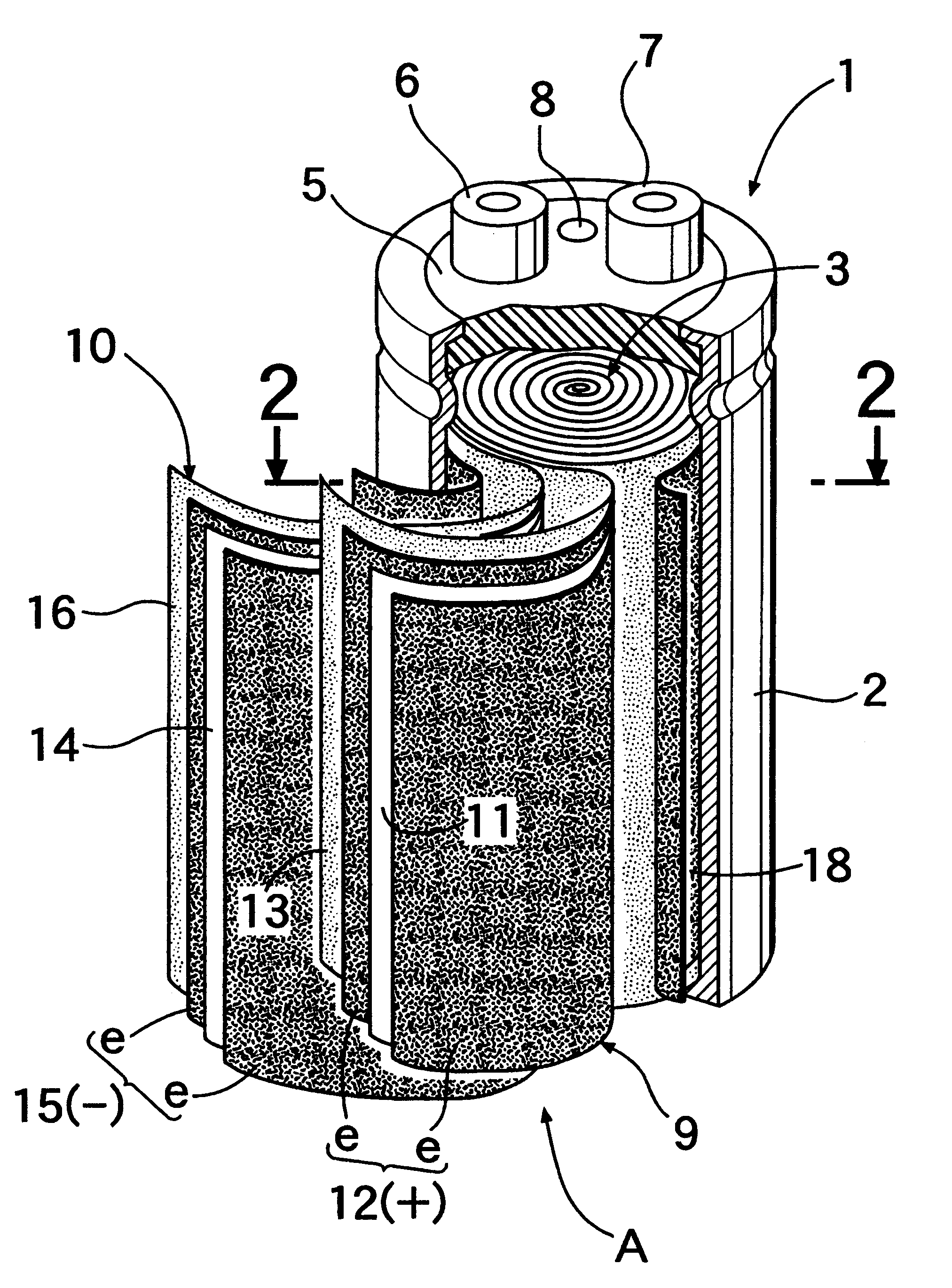
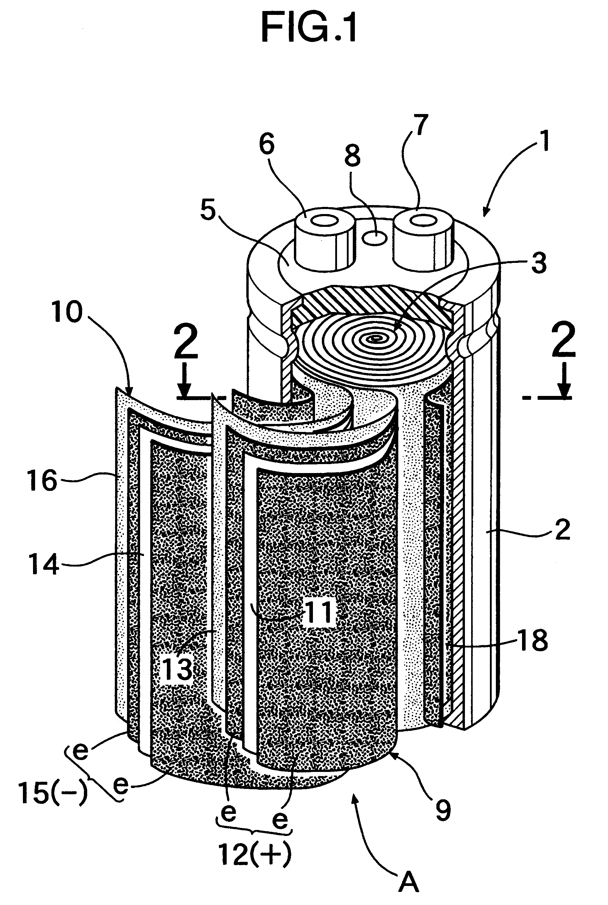
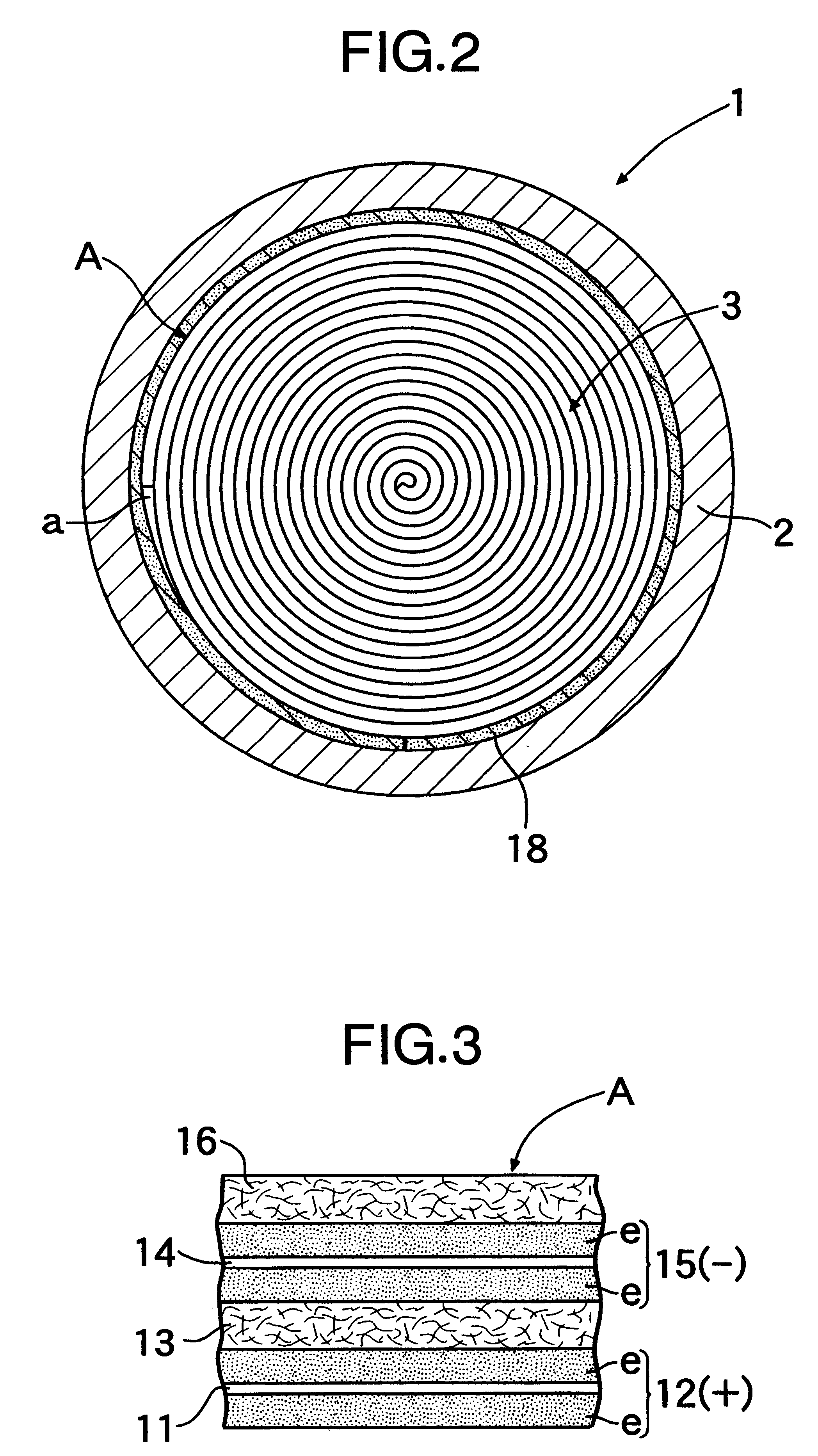
Tubular electric double-layer capacitor
a double-layer capacitor and electric double-layer technology, applied in the direction of electrolytic capacitors, wound capacitors, fixed capacitors, etc., can solve the problems of unbalance between potentials and performance deterioration, and achieve the effect of performance deterioration
- Summary
- Abstract
- Description
- Claims
- Application Information
AI Technical Summary
Benefits of technology
Problems solved by technology
Method used
Image

Examples
example
(2)
An electrode roll 3 having a diameter of about 49 mm was produced in the same manner as in Example (1). A band-shaped electrode having a width of 95 mm and a length of 157 mm was cut from the electrode sheet described in Example (1) and then bonded to one surface of a band-shaped collector having a width of 105 mm, a length of 157 mm and a thickness of 40 .mu.m using a conductive adhesive, thereby forming a band-shaped element. Thereafter, the band-shaped element was superposed on a second separator 16, and the resulting superposed assembly was wound around the outer peripheral surface of the electrode roll 3, and opposite ends thereof were abutted against each other and fixed by an adhesive tape, thereby forming a cylindrical electrode 18 having a length of 95 mm and a thickness of 175 .mu.m, and a cylindrical collector 19 in close contact with an outer peripheral surface of the cylindrical electrode 18 and having a length of 105 mm and a width of 40 .mu.m.
The electrode roll 3 h...
PUM
 Abstract
Description
Claims
Application Information