Laser optimized multimode fiber and method for use with laser and LED sources and system employing same

a multi-mode fiber and laser technology, applied in the field of laser opt, can solve the problems of excessively low bandwidth, not optimized, and typically not a practical solution for system owners

Inactive Publication Date: 2002-08-13
CORNING INC
View PDF13 Cites 32 Cited by
  • Summary
  • Abstract
  • Description
  • Claims
  • Application Information

AI Technical Summary

Problems solved by technology

However, as data rates begin to increase beyond the modulation capability of LEDs, system protocols are migrating away from LEDs, and instead, to laser sources.
Multimode optical fiber currently employed in telecommunication systems is designed primarily for use with LED sources and is generally not optimized for use with the lasers envisioned to operate in systems designed to transmit information at rates equal to or greater than one (1) gigabit / sec.
Consequently, small deviations in the fiber profile can produce significant perturbations in the impulse rise and fall, which can have a large effect on system performance.
This effect can manifest itself in the form of excessively low bandwidth, as excessively high temporal jitter, or both.
Although it is possible to correct these deficiencies to some degree by changing the launch condition of the source, such as the offset launch mode conditioning patch cord or the laser beam expander, this is typically not a practical solution for system owners.
However, next generation systems capable of gigabit / sec. and higher transmission rates cannot achieve all of these link lengths with standard multimode fiber presently available.
With such multimode optical waveguide fibers having standard "alpha" profiles, however, it is not possible to achieve an OFL bandwidth of 1000 MHz.km at 850 nm and 4000 MHz.km at 1300 nm.
Moreover, because such LANs are in their infancy, all of the system components necessary to meet and / or exceed transmission rates of one gigabit / sec. are not yet fully reduced or practiced, optimized, and / or tested.
For these reasons, it is not practical to replace existing LAN systems with a new LAN system speculatively designed to meet or exceed such high data rates.
While it may be possible to achieve this result, it will likely not be the preferred or optimal solution, as following such a course of action will likely result in costly upgrades to the system and potentially a rework of the entire system.

Method used


Image

  • Laser optimized multimode fiber and method for use with laser and LED sources and system employing same
  • Laser optimized multimode fiber and method for use with laser and LED sources and system employing same
  • Laser optimized multimode fiber and method for use with laser and LED sources and system employing same

Examples


example 1

One method of testing the performance of the laser optimized multimode fiber is to manufacture a fiber having the desired DMD characteristics and test it with a variety of laser sources. The results of such testing are shown in FIG. 6.

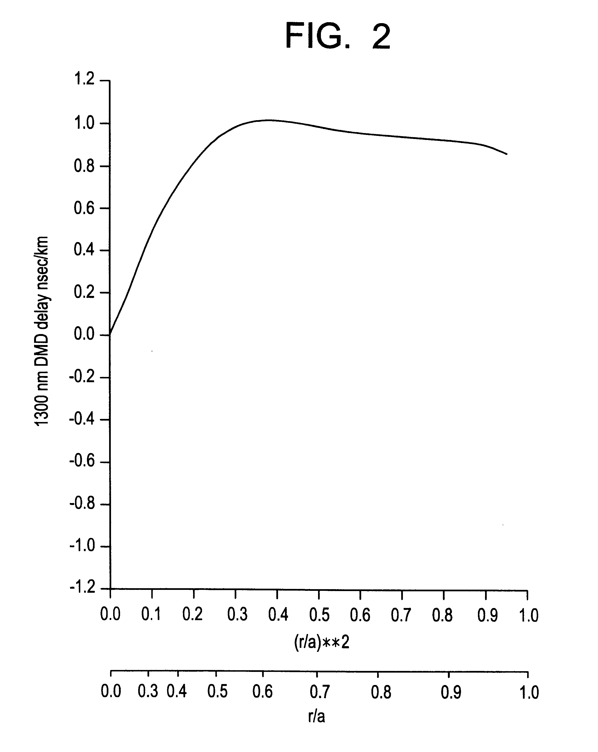
The `effective` bandwidth (MHz.km) of the multimode optical fiber characterized by the DMD profile depicted in FIGS. 2-3 and 7 is shown in FIG. 6 for a variety of 780 to 850 nm Gigabit Ethernet System lasers. The fiber's overfilled (OFL) bandwidth, measured using the standard measurement and launch techniques referenced earlier in this application, was 288 MHz.km at 850 nm and 1054 MHz.km at 1300 nm. The fiber's laser bandwidth, measured using the standard measurement and launch techniques referenced earlier in this application was 930 MHz.km at 850 nm (using the patchcord with a 23.5 um diameter core as well as a 850 nm source laser with an RMS spectral width less than 0.85 nm, as described earlier) and 2028 MHz.km at 1300 nm (using a Fabry-Perot lase...

example 2

As a second example, the fiber whose measured DMD is in FIG. 4 and whose measured index profile is in FIG. 8 was tested for OFL bandwidth, for `defined` laser bandwidth using the 23.5 um patchcord at 850 nm and the 4 um offset at 1300 nm, and for `effective` bandwidth with a set of 13 Gigabit Ethernet System lasers. The standard OFL bandwidth was measured at 564 MHz.km at 850 nm and 560 MHz.km at 1300 nm. The `defined` laser bandwidth at 850 nm using the patchcord with a 23.5 um diameter core was 826 MHz.km, while at 1300 nm the laser bandwidth defined by using a Fabry-Perot laser with a 4 um offset had a value of 5279 MHz.km. The `effective` bandwidths measured with 13 Gigabit Ethernet System lasers at 850 nm or 780 nm were as follows: 1214, 886, 880, 876, 792, 786, 754, 726, 614, 394, 376, 434 and 472 MHz.km. Again, the defined laser launch for 850 nm with a patchcord with a 23.5 um diameter core yields a bandwidth which approximates the `effective` bandwidth seen with a number of...


PUM

PropertyMeasurementUnit
diameteraaaaaaaaaa
lengthaaaaaaaaaa
lengthaaaaaaaaaa

Abstract

A multimode optical fiber having a first laser bandwidth greater than 220 MHz.km in the 850 nm window, a second laser bandwidth greater than 500 MHz.km in the 1300 nm window, a first OFL bandwidth of at least 160 MHz.km in the 850 nm window, and a second OFL bandwidth of at least 500 MHz.km in the 1300 nm window is disclosed. The multimode fiber is capable of operating in telecommunication systems employing both LED power sources and high power laser sources. Methods of making and testing the multimode optical fiber are also disclosed.

Description

1. Field of the InventionThe present invention relates generally to a multimode optical fiber and method for use with telecommunication systems employing low data rates, as well as systems employing high data rates, and more particularly, to a multimode optical fiber and method optimized for applications designed for state of the art laser sources, as well as common light emitting diode sources.While the present invention is subject to a wide range of applications, it is particularly well suited for use in telecommunications systems designed to transmit data at rates equal to and exceeding one gigabit / sec.2. Technical BackgroundThe goal of the telecommunication industry is generally to transmit greater amounts of information, over longer distances, in shorter periods of time. Over time, it has been shown that this objective is a moving target with no apparent end in sight. As the number of systems users and frequency of system use increase, demand for system resources increases as w...

Claims


Application Information

Patent Timeline
Patent Type & Authority Patents(United States)
IPC IPC(8): C03B37/014G02B6/02G02B6/028
CPCC03B37/01413G02B6/02G02B6/02214G02B6/0288C03B2201/31C03B2203/22C03B2203/26C03B2203/31C03B2203/36Y02P40/57
Inventor ABBOTT, III, JOHN S.HARSHBARGER, DOUGLAS E.
Owner CORNING INC
Why Eureka
Try Eureka