Gas processing apparatus baffle member, and gas processing method

a technology of gas processing apparatus and baffle member, which is applied in the direction of vacuum evaporation coating, chemical vapor deposition coating, coating, etc., can solve the problems of limiting the pressure on the upstream side of the baffle plate, machining accuracy, and cost restriction

Inactive Publication Date: 2002-08-20
TOKYO ELECTRON LTD
View PDF12 Cites 263 Cited by
  • Summary
  • Abstract
  • Description
  • Claims
  • Application Information

AI Technical Summary

Problems solved by technology

However, due to the restriction of the machining accuracy, the cost restriction, the limitation of the pressure on the upstream side of the baffle plate 47, and so forth, the hole diameters of the through-holes 46 cannot be satisfactorily decreased.
Thus, the gas cannot be uniformly supplied to the entire surface of the wafer 42.
Thus, according to the related art reference, gas cannot be uniformly supplied to the entire surface of the wafer.
When the backing pressure of the baffle member becomes large, the irregularity of the dynamic pressure of the gas due to the spray flow from the gas outlet of the gas delivery pipe decreases.
Thus, the irregularity of the backing pressure of the baffle member decreases.
When the backing pressure of the baffle member becomes large, the irregularity of the dynamic pressure of the gas due to the spray flow from the gas outlet of the gas delivery pipe decreases.
Thus, the irregularity of the backing pressure of the baffle member decreases.
The reason why the uniformity of the gas flow is represented with such an approximate expression is in that it is difficult to obtain the flow amount of the gas that flows in each spray hole and therefore the mass flow amount of the gas cannot be accurately obtained.

Method used


Image

  • Gas processing apparatus baffle member, and gas processing method
  • Gas processing apparatus baffle member, and gas processing method
  • Gas processing apparatus baffle member, and gas processing method

Examples


first embodiment

(First Embodiment)

Next, with reference to the accompanying drawings, a first embodiment of the present invention will be described. In the first embodiment, the present invention is applied to a CVD apparatus.

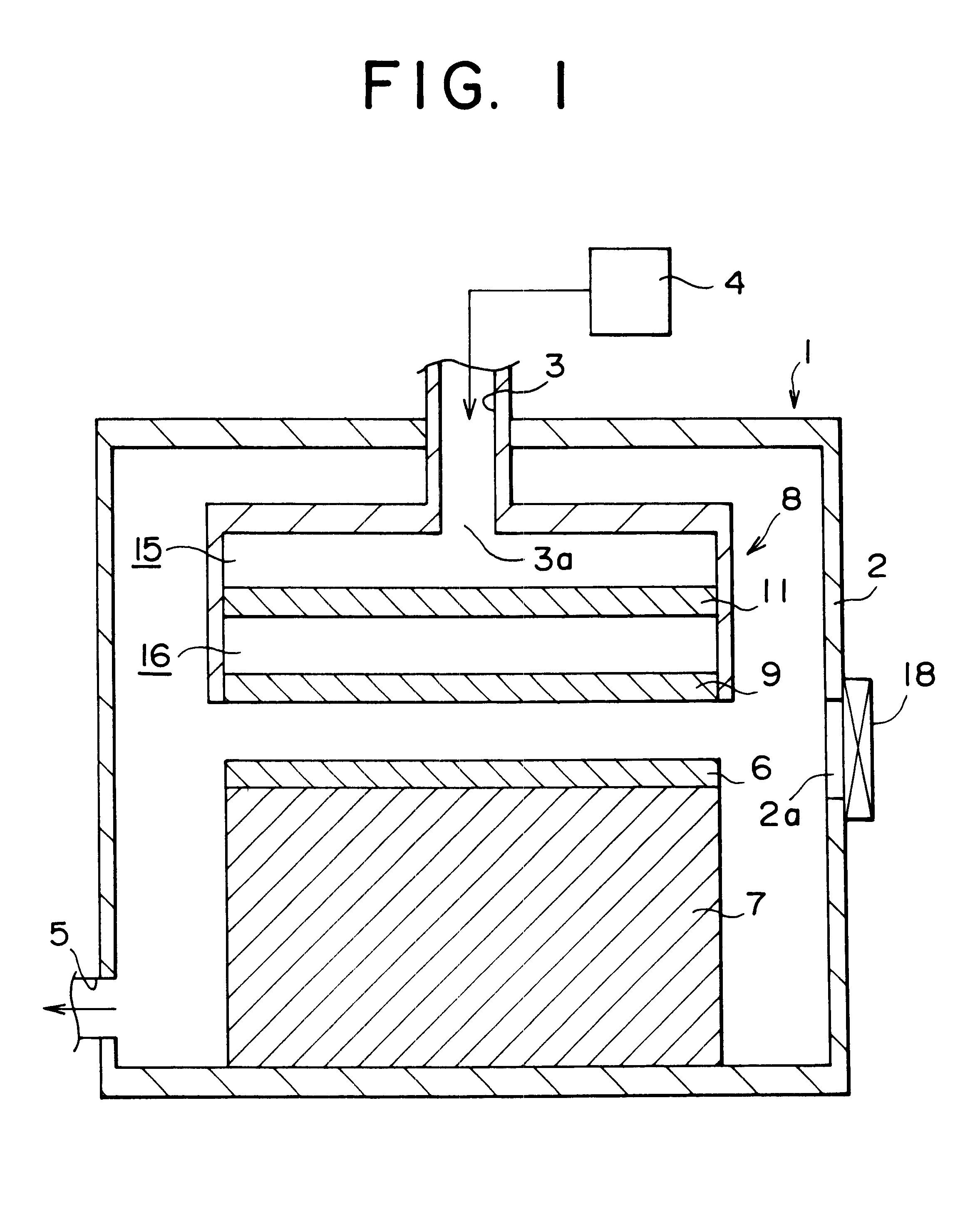
FIG. 1 is a sectional view showing the structure of a gas processing apparatus according to the first embodiment of the present invention.

As shown in FIG. 1, a processing chamber 2 of the gas processing apparatus 1 is airtightly structured and made of aluminum or the like. The processing chamber 2 has a heating mechanism and a cooling mechanism (not shown).

A gas delivery pipe 3 is connected to an upper center portion of the processing chamber 2. The gas delivery pipe 3 delivers gas to the interior of the processing chamber 2. The interior of the processing chamber 2 and the interior of the gas delivery pipe 3 are connected. The gas delivery pipe 3 is connected to a gas supply source 4. Gas is supplied from the gas supply source 4 to the gas delivery pipe 3. The gas is delivered...

example of first embodiment

In an example, the molecular weight of gas was 28 g / mol (nitrogen). The gas density was 2.55.times.10.sup.-3 kg / m.sup.3. The gas viscosity was 1.76.times.10.sup.-5 Pa.multidot.s. The inner temperature of the processing chamber was 27.degree. C. The inner pressure of the processing chamber was 1.7 Torr. The inner diameter of the gas delivery pipe 3 was 7 mm. The gas supply amount (gas flow amount) of the gas supply source 4 was 2000 sccm.

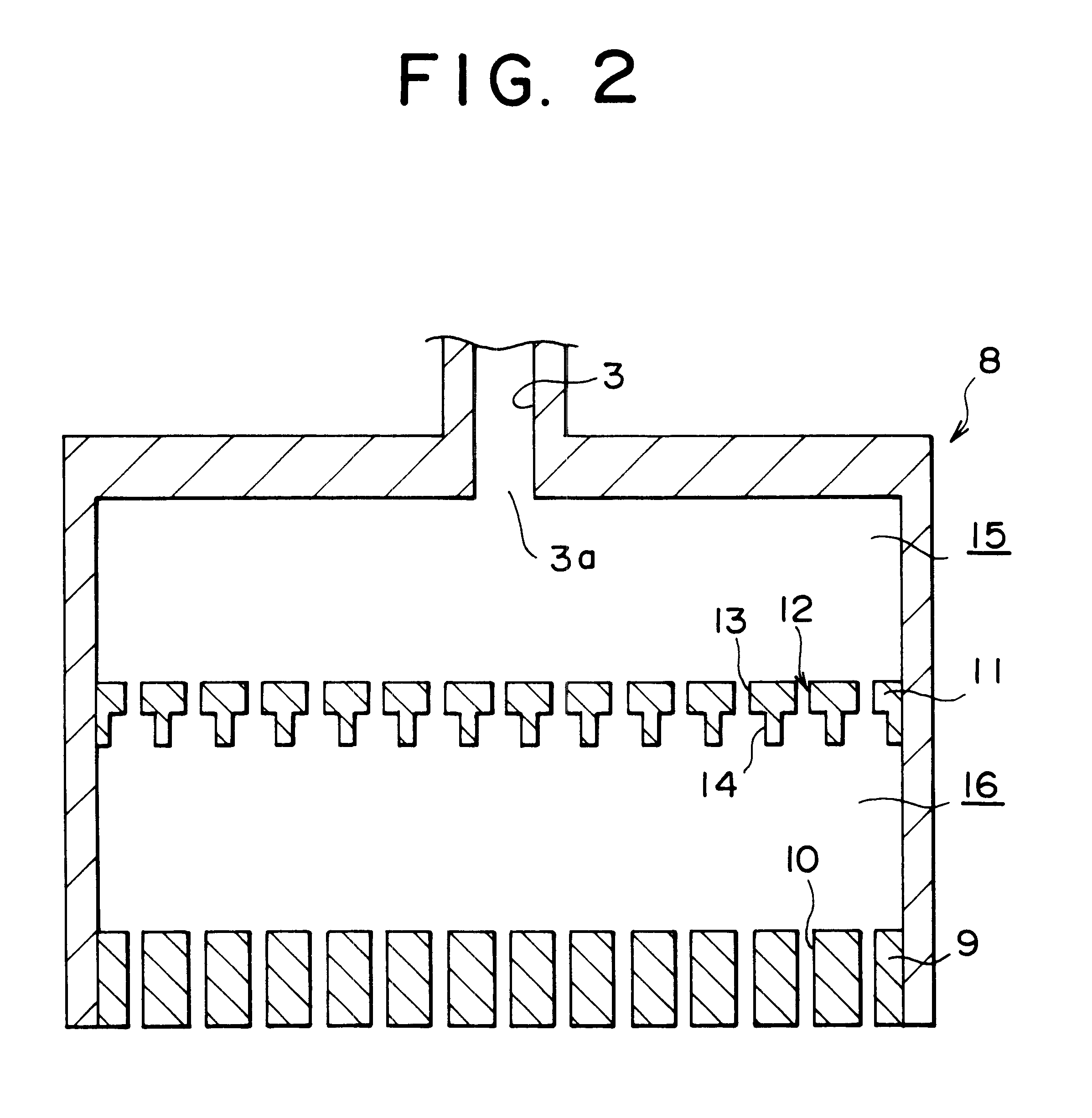
The plate thickness of the spray plate 9 was 10 mm. The spray plate 9 had 641 spray holes 10 that were uniformly formed on the entire surface thereof. The hole diameter of each spray hole 10 was 1 mm.

The plate thickness of the baffle plate 11 was 7 mm. The baffle plate 11 had 641 through-holes 12 that were uniformly formed on the entire surface thereof. The hole diameter L1 of the upper hole portion 13 of each through-hole 12 was 1 mm. The hole length of the upper hole portion 13 was 3.5 mm. The hole diameter L2 of the lower hole portion 14 of each t...

second embodiment

(Second Embodiment)

Next, with reference to the accompanying drawings, a second embodiment of the present invention will be described.

In the second embodiment, similar portions to those in the first embodiment are denoted by similar reference numerals and their description is omitted.

Next, the different points from the first embodiment will be mainly described.

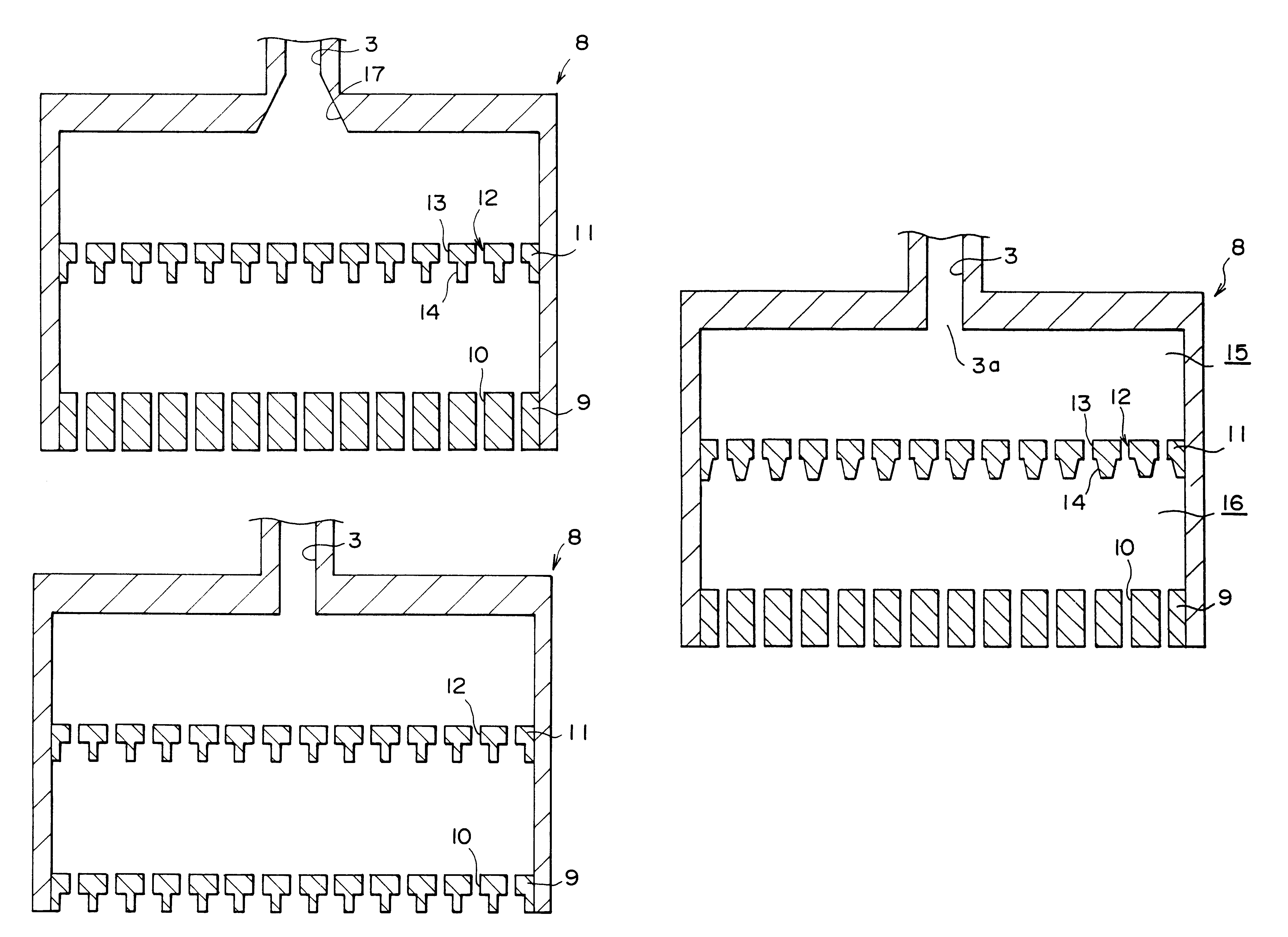
FIG. 6 is a sectional view showing the structure of a shower head 8 according to the second embodiment of the present invention.

As shown in FIG. 6, in the second embodiment, the baffle plate 11 according to the first embodiment is not disposed. In addition, the shape of the gas outlet of the gas delivery pipe 3 of the first embodiment was changed.

According to the second embodiment, a gas outlet 17 is connected to a processing chamber 2 of a gas delivery pipe 3. The gas outlet 17 spreads toward a shower head 8. The gas outlet 17 spreads with a spread angle in the range of 0.5 to 45 degrees, preferably in the range from 1 to 30 d...


PUM

PropertyMeasurementUnit
spread angleaaaaaaaaaa
diameteraaaaaaaaaa
spread angleaaaaaaaaaa

Abstract

A gas processing apparatus is disclosed, that comprises a processing chamber that is airtightly structured, a gas delivery pipe connected to the processing chamber, a gas supply source for supplying gas to the processing chamber through the gas delivery pipe, a holding table for holding a workpiece loaded to the processing chamber, a shower member disposed at a gas outlet of the gas delivery pipe connected to the processing chamber, a spray plate structured as a partition wall of the shower member that faces the holding plate, the spray plate having a plurality of spray holes, and a baffle member disposed between the spray plate in the shower member and the gas outlet and having a plurality of through-holes formed perpendicular to the surface of the baffle member, wherein each of the through-holes of the baffle member has a first opening portion and a second opening portion facing the gas outlet, the second opening portion facing the spray plate, the opening area of the second opening portion being larger than the opening portion of the first opening portion. Thus, a gas processing apparatus and a gas processing method that allow gas to be uniformly supplied to the entire surface of a workpiece are provided. In addition, a baffle member for use with the gas processing apparatus and the gas processing method is provided.

Description

1. Field of the InventionThe present invention relates to a gas processing technology, in particular, to a gas processing apparatus, a baffle member, and a gas processing method for use in fabrication of semiconductor devices.2. Description of the Related ArtWhen semiconductor devices are fabricated, a gas processing apparatus that supplies various types of gas to a processing chamber and performs a predetermined process for a workpiece is used.As an example of such a gas processing apparatus, a CVD (Chemical Vapor Deposition) apparatus is known.In the CVD apparatus, various types of gas as row materials are supplied to a workpiece such as a wafer disposed in a processing chamber. Using thermal energy of the wafer, plasma excitation, and so forth, gas as a chemically active reaction seed causes a thin film to be formed on the wafer. Thus, to equally form a thin film on the entier surface of the wafer using such an apparatus, it is necessary to uniformly supply the gas to the entire ...

Claims


Application Information

Patent Timeline
Patent Type & Authority Patents(United States)
IPC IPC(8): C23C16/455H01J37/32C23C16/44H01L21/302C23C14/24H01L21/205H01L21/3065
CPCC23C16/455C23C16/45514C23C16/45565H01J37/3244C23C16/45574C23C16/45591H01J37/32633H01J2237/3321H01J2237/3323
Inventor KASAI, SHIGERUIWATA, TERUOKOMIYA, TAROYONENAGA, TOMIHIRO
Owner TOKYO ELECTRON LTD
Why Eureka
Try Eureka