
Flammable liquids

a technology of flammable liquids and fuel tanks, which is applied in the direction of water supply tanks, gas/liquid distribution and storage, packaging, etc., can solve the problems of limited fuel loss, severe disablement or destruction of aircraft at worst, and the fuel tank is one of the most vulnerable parts insid

Inactive Publication Date: 2002-09-17
BAE SYSTEMS PLC
View PDF22 Cites 22 Cited by
  • Summary
  • Abstract
  • Description
  • Claims
  • Application Information

AI Technical Summary

Benefits of technology

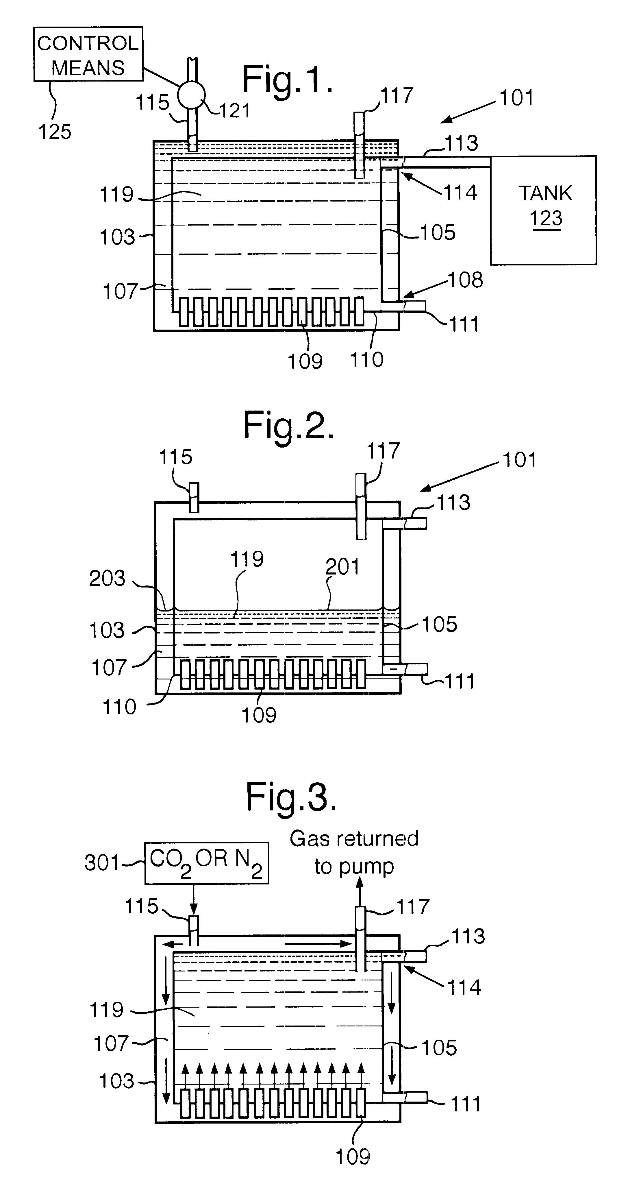
The present invention provides control in the creation of the protective barrier and this enables the protective barrier to be formed at any time on demand. Furthermore when the displacing means is activated, any fuel present in the first chamber can be transferred into the second chamber to maximise the amount of protected fuel storage available at that instant in time.
Preferably, the second chamber is contained substantially within the first chamber. This provides improved dimensional protection of the second chamber and reduces the possibility of the hydrodynamic ram effect occurring on impact of a projectile. In fact, the liquid retaining walls of the second chamber may together form a cavity surrounding the second chamber such that the displacing means is arranged to create the protective barrier substantially surrounding the second chamber in use. This advantageously provides maximum protection from the effects of hydrodynamic ram caused by projectile penetration because a penetrating projectile from any direction will never encounter a liquid retaining wall. Any projectile would also have to pass through two tank walls before gaining contact with the flammable liquid.
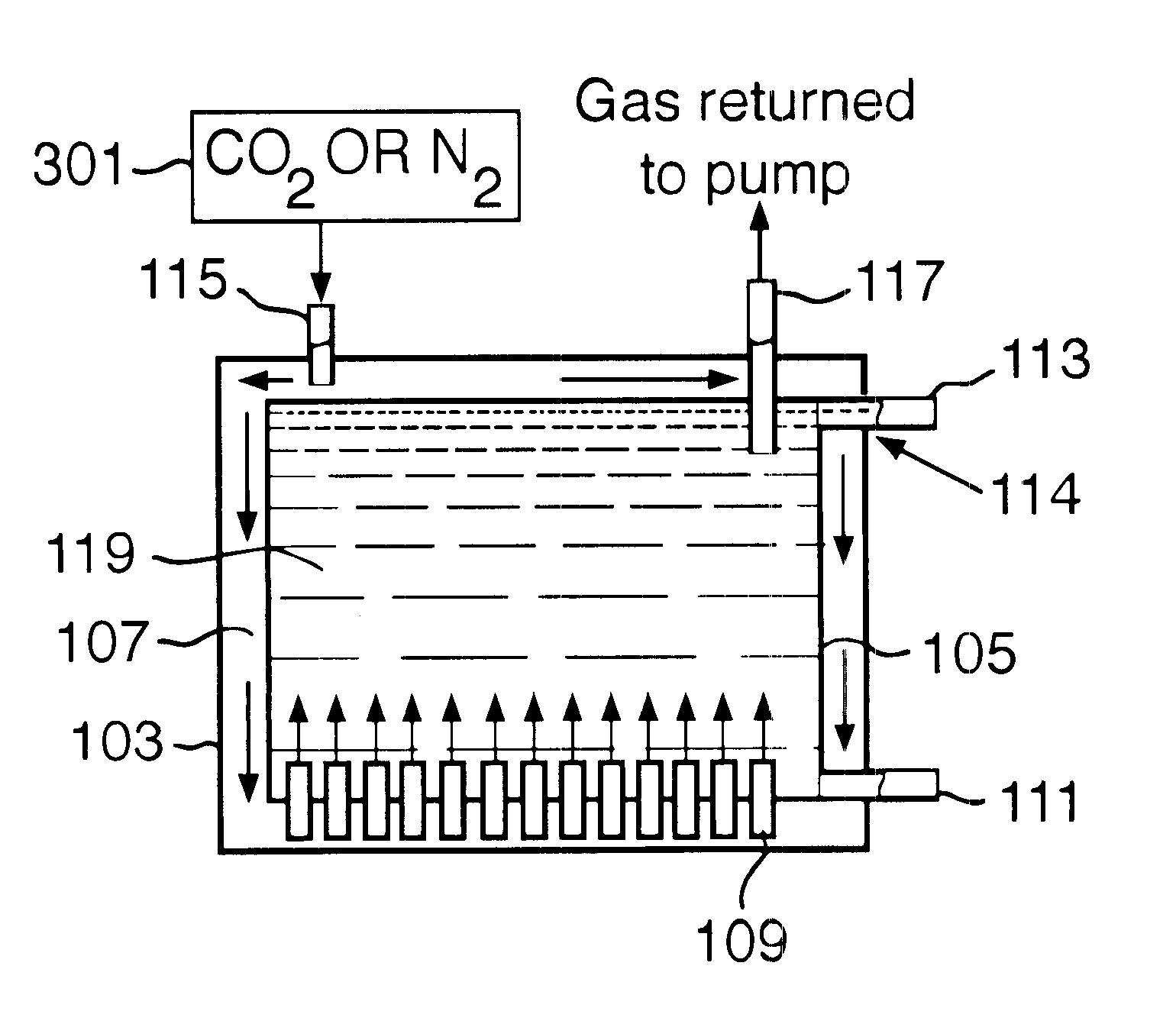
The displacing means may be arranged to introduce a gas into the first chamber to effect the displacement of the liquid into the second chamber. The resulting protective layer of gas is able to dissipate the pressure waves generated by the intrusion of the projectile, as it is readily compressible in comparison to the non-flammable liquid. Consequently any exit aperture of the projectile will be comparable in size to its entrance aperture, preventing the sudden escape of a large quantity of fuel. Preferably, the gas is non-flammable thereby extinguishing any projectile's burning trail and, more preferably, the gas is substantially inert (like, for example, nitrogen or carbon dioxide), providing no storage hazard.
The container may further comprise collecting means for collecting the gas from the second chamber and recycling the gas for use with the displacing means. In this way, the amount of gas required to maintain the protective barrier is minimised, thereby improving space and weight characteristics over prior art systems.

Problems solved by technology

The fuel tank is one of the most vulnerable components within a military aircraft when it is under attack, particularly during low-level flying operations.
Penetration of the tank can result in limited loss of fuel at best, but severe disablement or destruction of the aircraft at worst.
If the tank is pierced by an incendiary projectile, the projectile's burning trail can ignite the fuel load and cause a devastating, rapidly progressive fire.
However, penetration alone by projectiles of a sufficiently large diameter can cause catastrophic failure of the tank by way of hydrodynamic ram effects within liquid fuel.
Although the liquid is able to dissipate this wave quickly, the liquid is relatively incompressible and is unable to absorb the pressure waves generated by the projectile as it traverses the tank.
Large quantities of fuel can then be drawn into the engine of the aircraft, causing an explosion of massive proportions.
This method of protection is not effective against larger caliber projectiles, such as 23 mm HEI (high explosive incendiary) ammunition, which as well as producing apertures which are too large to be self-sealed, also generate considerable hydrodynamic ram effects within the fuel.
The required protection is only available once the fuel in the auxiliary tank has been used up and this can present a problem for protection of the tank at an early stage in the aircraft's mission.
Also separate pumps are required for the auxiliary tank and the main tank, which increases the weight of the fuel distribution system.
The limited protection afforded by this device is not available initially and so the aircraft can be vulnerable for an initial period of time.
The previous attempts to reduce catastrophic fuel tank failure thus far have had only limited success.

Method used


Image

  • Flammable liquids
  • Flammable liquids

Examples


Embodiment Construction

Referring to FIG. 1, an aircraft fuel tank 101 embodying the present invention is now described together with its operation in an aircraft. The aircraft fuel tank 101 comprises an outer chamber 103 and an inner chamber 105. Inner chamber 105 is substantially contained within the outer chamber 103, providing the inner chamber 105 with a surrounding cavity 107. The fuel tank 101 comprises thirteen open-ended pipes 109 provided at a lower portion (base) 108 of the inner chamber 105 protruding above and below a base wall 110. These open-ended pipes 109 provide a fluid communication between the inner and outer chambers 105 and 103, respectively. A fuelling pipe 111 is also provided at the lower portion 108 of the inner chamber 105 for supplying fuel from the tank 101 to the aircraft's jet engines (not shown), whilst an overflow pipe 113 exits from an upper portion 114 of the inner chamber 105 and provides a means for removing excess fuel from the tank 101. An entrance pipe 115 to the fue...


PUM


Abstract

An aircraft fuel tank (101) comprises an inner and an outer chamber (103, 105) which are fluidly interconnected via a plurality of open-ended pipes (109). A non-flammable gas, which is immiscible with the fuel (119), is pumped into the outer chamber (103) on demand to displace the fuel (119) into the less vulnerable inner chamber (105) and thereby forms a protective non-flammable gaseous barrier around the fuel-retaining inner chamber (105). The fuel tank (101) is used primarily for military aircraft and provides the ability to attenuate hydrodynamic ram effects arising in the fuel following penetration of the fuel tank (101) by a projectile. All round protection is achieved because the inner chamber (105) is contained wholly within the outer chamber (103).

Description

1. Field of the InventionThe present invention concerns improvements relating to flammable liquid storage, namely a container for storing flammable liquid and a method of reconfiguring the container to obviate so-called hydrodynamic ram effects within the liquid. More particularly, though not exclusively, the present invention relates to a fuel tank of a military aircraft, aiming to reduce the risk of catastrophic failure of the tank following penetration by a projectile.2. Discussion of Prior ArtThe fuel tank is one of the most vulnerable components within a military aircraft when it is under attack, particularly during low-level flying operations. Penetration of the tank can result in limited loss of fuel at best, but severe disablement or destruction of the aircraft at worst.If the tank is pierced by an incendiary projectile, the projectile's burning trail can ignite the fuel load and cause a devastating, rapidly progressive fire. However, penetration alone by projectiles of a su...

Claims


Application Information

Patent Timeline
IPC IPC(8): B64D37/00B64D37/32
CPCB64D37/32Y10T137/3127Y10T137/86228Y10T137/469Y10T137/4824
Inventor CONSTANTINOU, CHRISOSTOMOS
Owner BAE SYSTEMS PLC
Learn More