
Engine component arrangement for outboard motor

a technology for engine components and outboard motors, which is applied in the direction of steam power plants, lubricant mounting/connection, vessel construction, etc., can solve the problems of large power heads obstructing the vision field of watercraft operators, large power heads can be significant sources of wind drag,

Inactive Publication Date: 2002-09-17
SANSHIN KOGYO CO LTD
View PDF25 Cites 27 Cited by
  • Summary
  • Abstract
  • Description
  • Claims
  • Application Information

AI Technical Summary

Benefits of technology

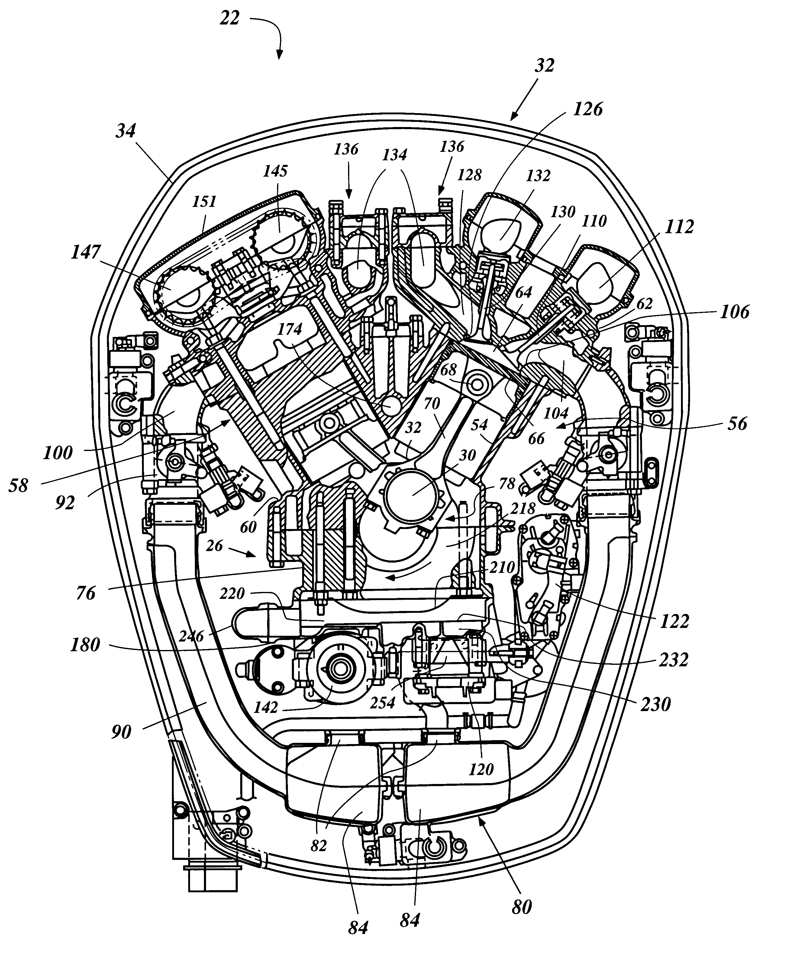
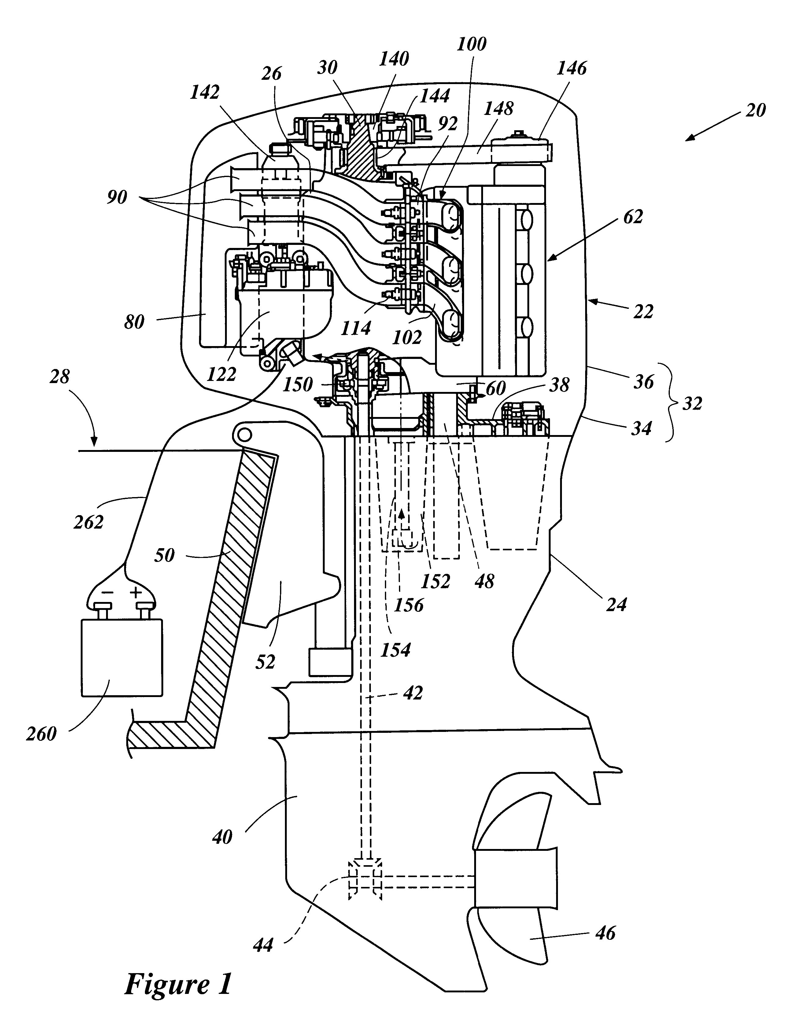
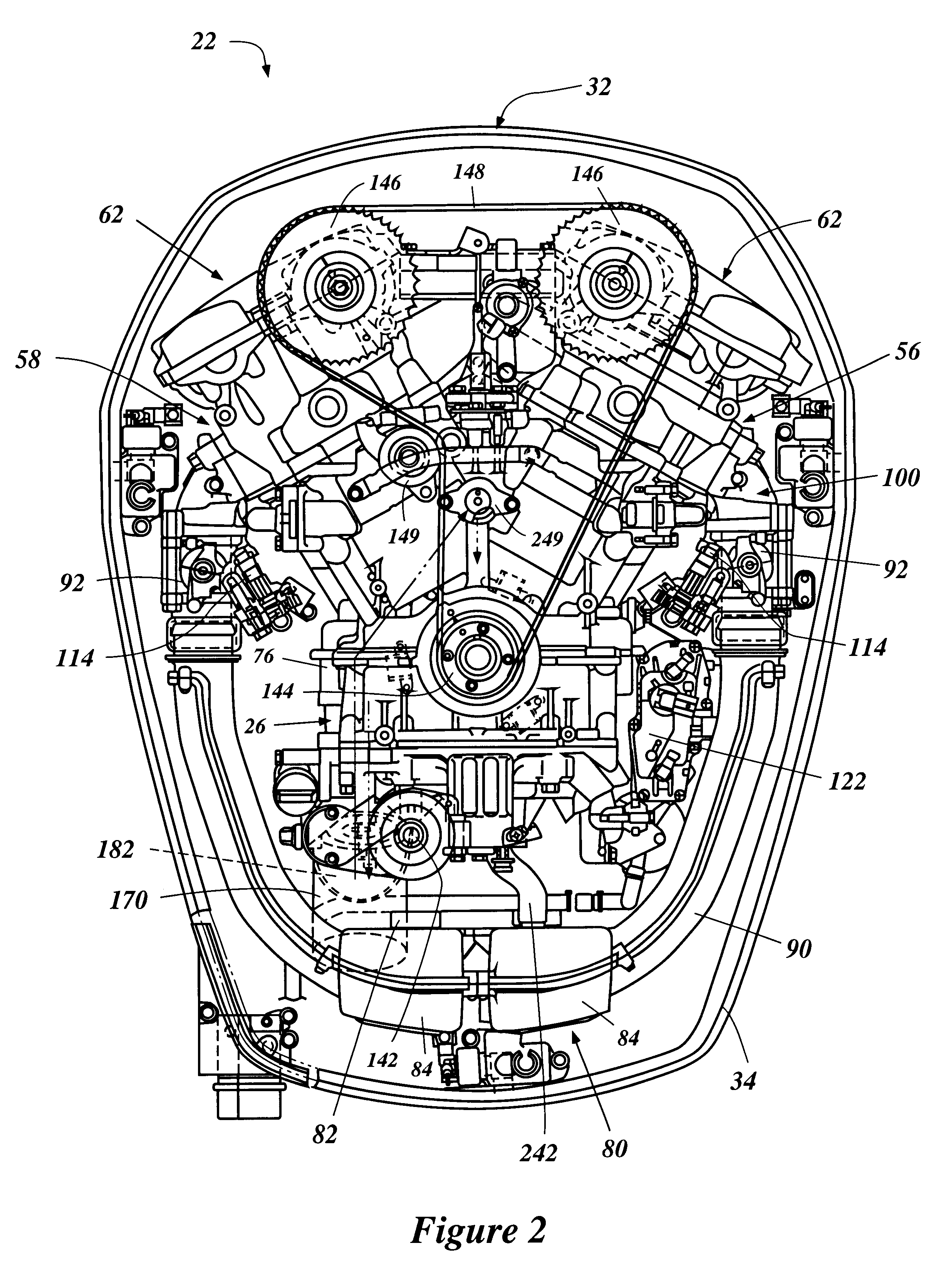
With reference initially to FIG. 1, an outboard motor 20 is illustrated therein. The illustrated outboard motor advantageously incorporates a four-stroke V-type engine having an oil filter and certain electrical components arranged and configured in accordance with certain features, aspects, and advantages of the present invention. The configuration results in a more compact motor construction. Although the component arrangement is described below in connection with the illustrated outboard motor, it should be understood that certain features, aspects, and advantages of the present invention can also be used in other applications such as, for example, but without limitation, two-stroke engines and a variety of other land-based vehicle and engine applications.

Problems solved by technology

As such, the power head can be a significant source of wind drag for the watercraft.
Also, a large power head may obstruct the watercraft operator's field of vision.
However, V-type engines tend to be relatively wide because of the inclined cylinder banks.

Method used


Image

  • Engine component arrangement for outboard motor
  • Engine component arrangement for outboard motor
  • Engine component arrangement for outboard motor

Examples


Embodiment Construction

With reference initially to FIG. 1, an outboard motor 20 is illustrated therein. The illustrated outboard motor advantageously incorporates a four-stroke V-type engine having an oil filter and certain electrical components arranged and configured in accordance with certain features, aspects, and advantages of the present invention. The configuration results in a more compact motor construction. Although the component arrangement is described below in connection with the illustrated outboard motor, it should be understood that certain features, aspects, and advantages of the present invention can also be used in other applications such as, for example, but without limitation, two-stroke engines and a variety of other land-based vehicle and engine applications.

The illustrated outboard motor 20 generally comprises a power head 22 and a driveshaft housing 24. The power head 22 preferably contains an internal combustion engine 26 that is used to power a watercraft 28 to which the outboar...


PUM


Abstract

An outboard motor has various electrical components mounted on a front side of the crankcase chamber. The crankcase chamber is connected by an electrical line to a negative terminal of a battery in an associated watercraft in order to ground the crankcase chamber. Thus, the electrical components are easily grounded by being connected to the crankcase chamber. An intake silencer of the engine induction system is positioned adjacent the crankcase chamber and at least one of the electrical components is disposed between the silencer and the crankcase member. An oil filter mount is also disposed on the front side of the crankcase chamber. The mount is adapted so that the oil filter can be installed thereon and is tilted along an inclined axis.

Description

PRIORITY INFORMATIONThis application is based on and claims priority to Japanese Patent Application No. Hei 11-283238, filed Oct. 4, 1999, the entire contents of which is hereby expressly incorporated by reference.1. Field of the InventionThe present invention principally relates to engines for powering an outboard motor. More particularly, the present invention relates to an arrangement of certain components for such engines associated with outboard motors.2. Description of the Related ArtOutboard motors are often used to power watercraft. The motors are attached to the transom of the watercraft and include an engine disposed within a power head of the motor. The engine drives a propulsion unit and is thus able to push the watercraft through water.The powerhead of the outboard motor comprises the engine enclosed within a cowling. The power head usually extends above a transom of the watercraft. As such, the power head can be a significant source of wind drag for the watercraft. Als...

Claims


Application Information

Patent Timeline
Patent Type & Authority Patents(United States)
IPC IPC(8): F01M11/03F02B75/00F02B75/22F02B61/00F02B61/04F02M35/104F02M35/10F02M35/12F02M35/116F02B75/02F02B75/18F02B77/00F02B67/00
CPCF01M11/03F02B61/045F02B75/22F02M35/10085F02M35/10144F02M35/10216F02M35/116F02M35/12F02M35/167F01P2050/02F01P2050/30F02B2075/027F02B2075/1824
Inventor KASHIMA, YUKINORIWATANABE, HITOSHI
Owner SANSHIN KOGYO CO LTD
Learn More