System for detection of obstructions in a motorized door system

a technology for obstruction detection and motorized doors, applied in the direction of motor/generator/converter stoppers, motor/electric converter control, instruments, etc., can solve the problems of door which attempts to continue a closing stroke, passenger injuries, and general unreliable edge sensors

Inactive Publication Date: 2002-09-17
WESTINGHOUSE AIR BRAKE CO
View PDF14 Cites 39 Cited by
  • Summary
  • Abstract
  • Description
  • Claims
  • Application Information

AI Technical Summary

Benefits of technology

It is an additional object of the present invention to provide an obstruction detection system for a motorized door which operates quickly upon encountering an obstruction.

Problems solved by technology

This requirement must be seriously considered because transit vehicle doors may be quite massive and such doors are generally moved quickly between the open and closed positions.
Forces required for rapid movement of massive doors are generally sufficient to cause injury to a passenger.
Such leading edge sensors are generally unreliable, in part because floating cables must be connected to the moving door panels.
Any failure of the edge sensor, or the cable connecting it to the control system for the door, may result in a door which attempts to continue a closing stroke, even after contacting a passenger.
This method has been found to be extremely inaccurate because the current drawn by the motor can vary widely due to aging and to temperature.
As is generally well known, aging reduces the strength of the field magnet (generally a permanent magnet).
Furthermore, this method can only detect a very substantial impact.

Method used


Image

  • System for detection of obstructions in a motorized door system
  • System for detection of obstructions in a motorized door system
  • System for detection of obstructions in a motorized door system

Examples


Embodiment Construction

, particularly, when the detailed description is taken in conjunction with the attached drawing figures and with the appended claims.

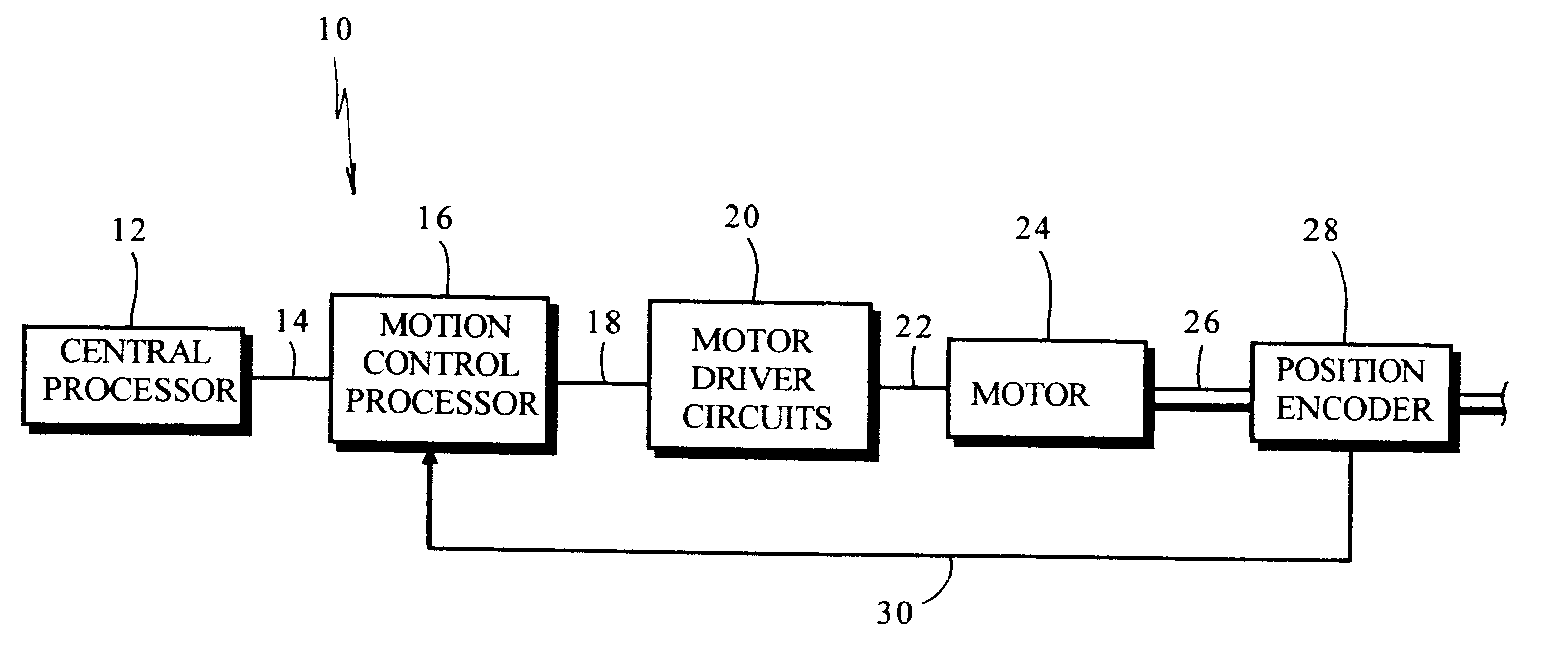
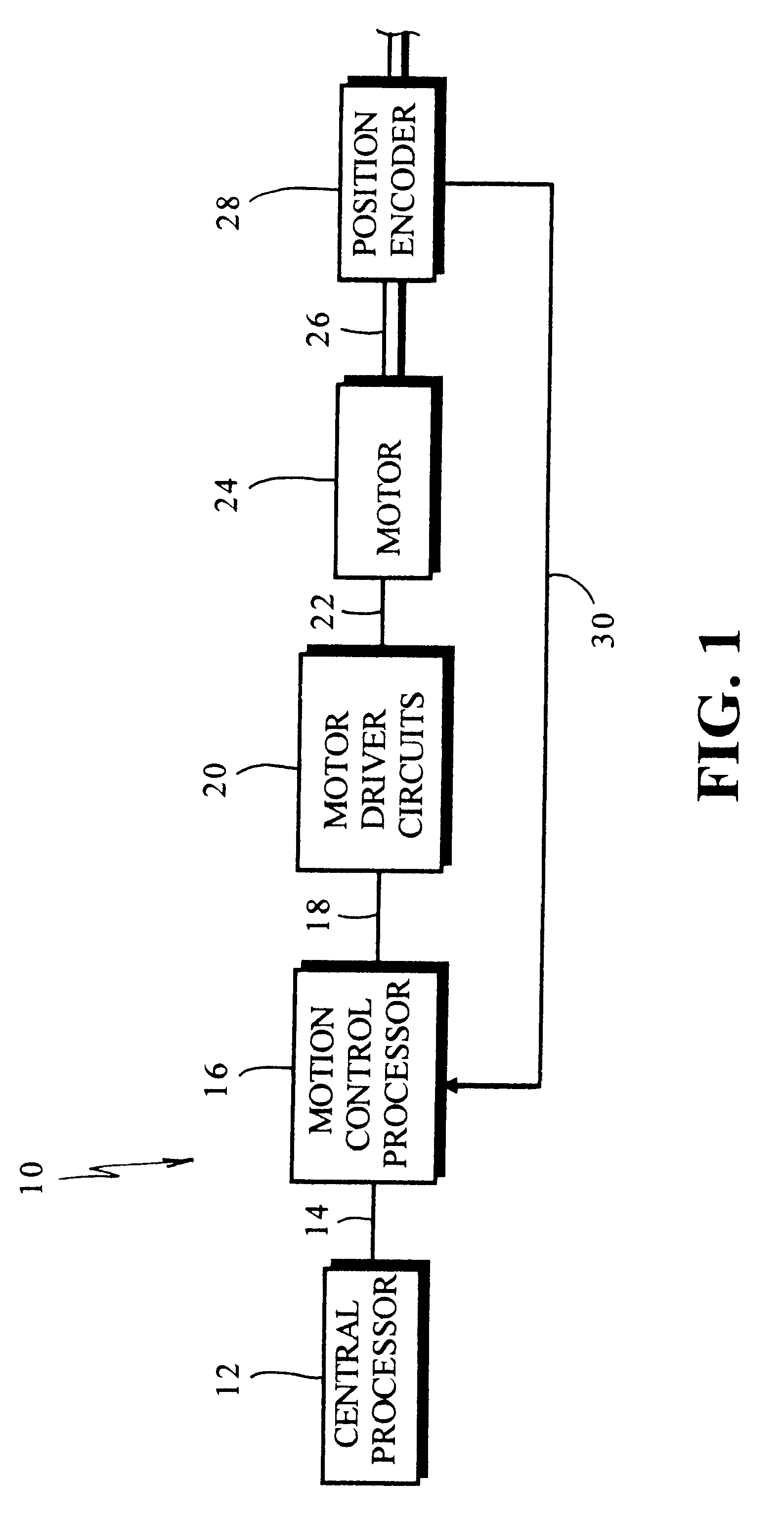
FIG. 1 is a schematic illustration of a presently preferred embodiment of the invention;

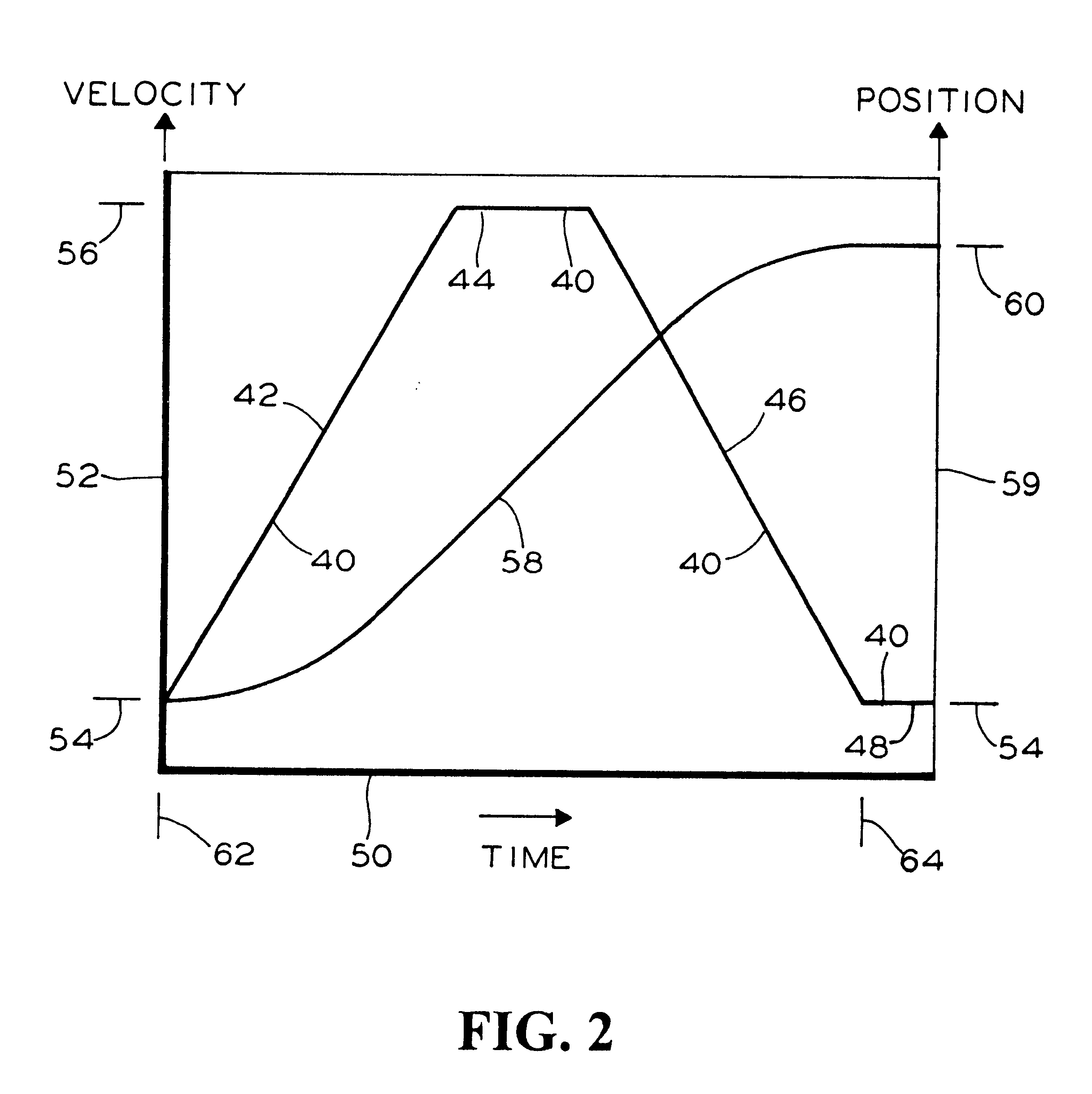
FIG. 2 is a plot showing ideal profiles for door velocity and distance traveled versus time;

FIG. 3 is a plot showing allowable envelopes for the door velocity for various segments of the stroke;

FIG. 4 is a plot showing departure from the envelope when an obstruction is detected;

FIG. 5 is a flowchart of the process of detecting obstructions during a stroke of the door based on a velocity discrepancy of the door;

FIG. 6 is a flowchart of the process of detecting obstructions during a stroke of the door based on a rate of change of velocity with time;

FIG. 7 is a flowchart of the presently preferred method of the invention in which different tolerances are permitted in different portions of the stroke; and

FIG. 8 is a flowchart of a method of detecting obstructions during...


PUM


Abstract

Method of detecting obstructions encountered by a motorized door. The method includes providing a signal processor with one or more signals indicative of a predetermined door trajectory profile for at least a segment of a stroke of the door, the door trajectory profile providing an ideal speed and / or position versus an elapsed time since a beginning of the segment of the stroke. A door position signal from a position encoder for the door is received into the signal processor. The method includes generating one or more signals indicative of the velocity and / or position of the door from the door position signal and generating a trajectory discrepancy signal based on the velocity and / or position in relation to the ideal speed and / or position. A motor control signal is generated based on the trajectory discrepancy signal and the motor control signal is connected to motor control circuits connected to drive the motor for the door. The method further includes performing one or more tests on either the trajectory discrepancy, the velocity of the door or the position of the door to determine whether the door has encountered an obstruction, in which case an obstruction detection signal is generated. The obstruction detection signal is for stopping the door.

Description

The present invention relates, in general, to control systems for powered doors and, more particularly, the instant invention relates to a powered door control system for a passenger transit type vehicle.Motor driven transit vehicle door systems require a system for detecting obstructions to protect a passenger who may be in the path of a door which is closing or opening as would be the case with outside sliding door(s). This requirement must be seriously considered because transit vehicle doors may be quite massive and such doors are generally moved quickly between the open and closed positions. Forces required for rapid movement of massive doors are generally sufficient to cause injury to a passenger. This would be the case, particularly, on the closing cycle when a passenger may be caught by the closing door(s).Prior to the development of the present invention, one method which has been employed is to place leading edge sensors in the seals adjacent the edge of a door which close...

Claims


Application Information

Patent Timeline
Patent Type & Authority Patents(United States)
IPC IPC(8): B61D19/00B61D19/02E05F15/00
CPCB61D19/026E05F15/40E05Y2201/214E05Y2201/232E05Y2400/302E05F15/41E05Y2900/51E05Y2800/00E05Y2400/554
Inventor CALAMATAS, PHILIP J.
Owner WESTINGHOUSE AIR BRAKE CO
Why Eureka
Try Eureka