
Exhaust system for 4-cycle engine of small watercraft

a technology of exhaust system and watercraft, which is applied in the direction of motor-driven power plants, special-purpose vessels, vessel construction, etc., can solve the problems of less height, less discomfort in sitting in a position, and reduced the ability of the rider to absorb the impact force with his or her legs

Inactive Publication Date: 2002-09-24
SANSHIN KOGYO CO LTD
View PDF15 Cites 40 Cited by
  • Summary
  • Abstract
  • Description
  • Claims
  • Application Information

AI Technical Summary

Benefits of technology

This configuration reduces emissions by improving the design and manufacturing of exhaust manifolds, allowing for more efficient heat management and compactness, while maintaining engine performance and stability.

Problems solved by technology

While the position of the rider--with his or her feet positioned wide apart and his or her legs straddling the seat--provides good stability, this stance reduces the ability of the rider to absorb with his or her legs impact forces as the watercraft bounds over wakes.
In addition, some smaller riders with less height find it uncomfortable to sit in a position with their feet widely spaced apart when straddling the seat.
One particular disadvantage of a two-cycle engine though, is emissions content.
However, when steps are taken to reduce the emissions content of a two-cycle engine, other generally undesirable consequences result, such as an increase in the weight of the engine, cost of manufacture, and reduction of its power output.
In the design and manufacture of exhaust manifold, a difficultly arises in shaping the exhaust runners so as to have approximately the same length.
An exhaust manifold having exhaust runners with varying shapes is difficult to manufacture.
In particular, some exhaust manifolds are monolithically cast from metal to improve a heat-resistant characteristic.
Thus, an exhaust manifold having more than two exhaust runners with varying shapes is particularly difficult to manufacture.
Further, where the exhaust manifold is water-cooled, the varying shapes of the exhaust runners provides an additional difficulty in manufacturing a cooling jacket disposed thermal communication with the exhaust manifold.
However, some applications for internal combustion engines cannot provide large amounts of free space adjacent the desired position of the engine body.
While the position of the rider--with his or her feet positioned wide apart and his or her legs straddling the sea --provides good stability, this stance reduces the ability of the rider to absorb with his or her legs impact forces as the watercraft bounds over wakes.
In addition, some smaller riders with less height find it uncomfortable to sit in a position with their feet widely spaced apart when straddling the seat.
Thus, the overall width available for the engine in such a watercraft is limited.

Method used


Image

  • Exhaust system for 4-cycle engine of small watercraft
  • Exhaust system for 4-cycle engine of small watercraft
  • Exhaust system for 4-cycle engine of small watercraft

Examples


Embodiment Construction

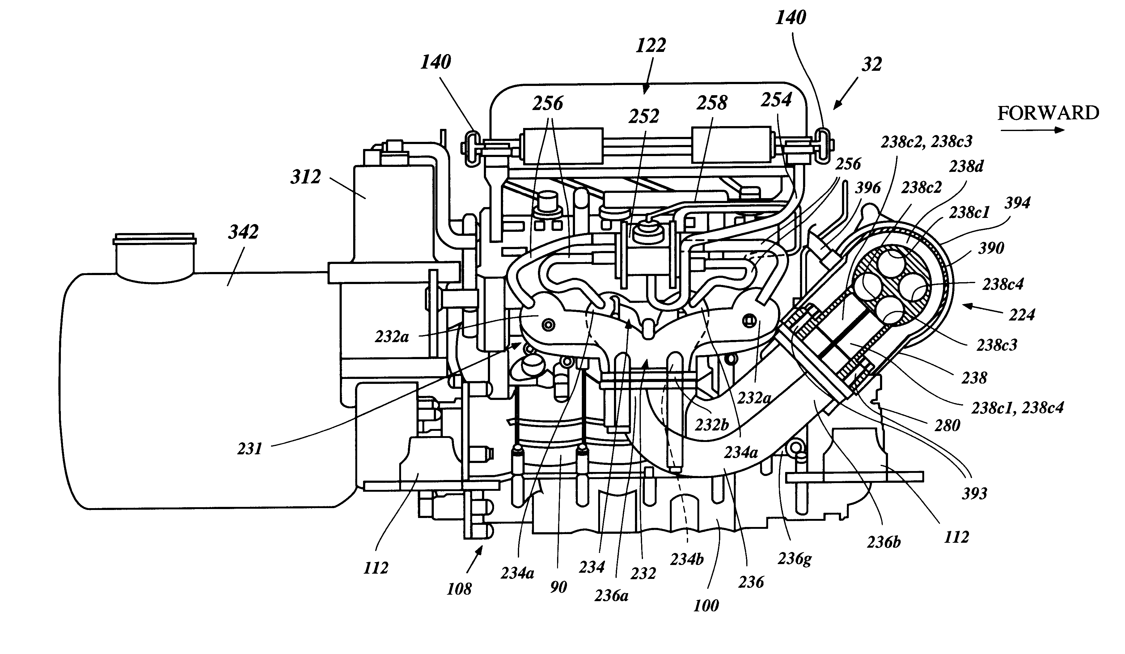
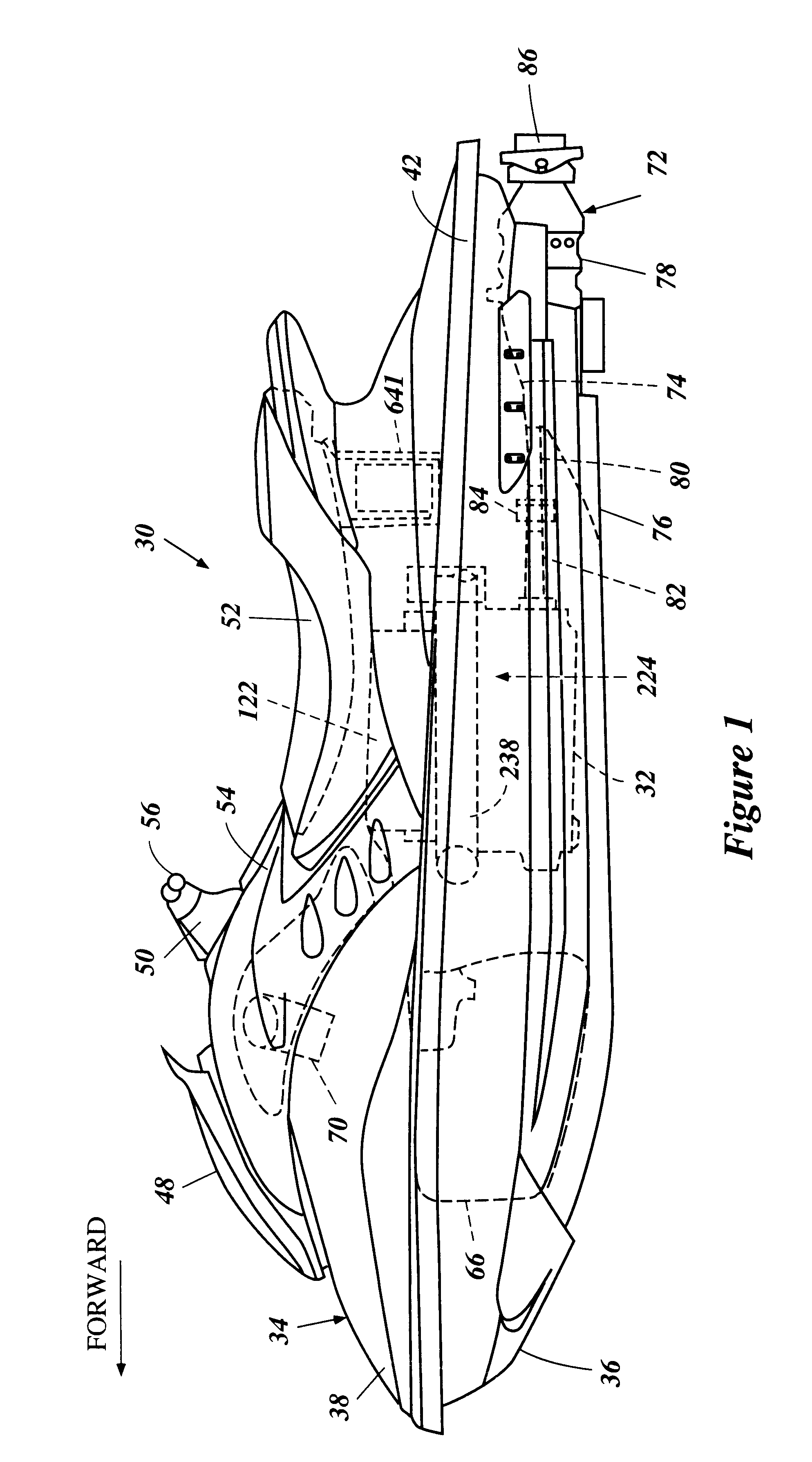
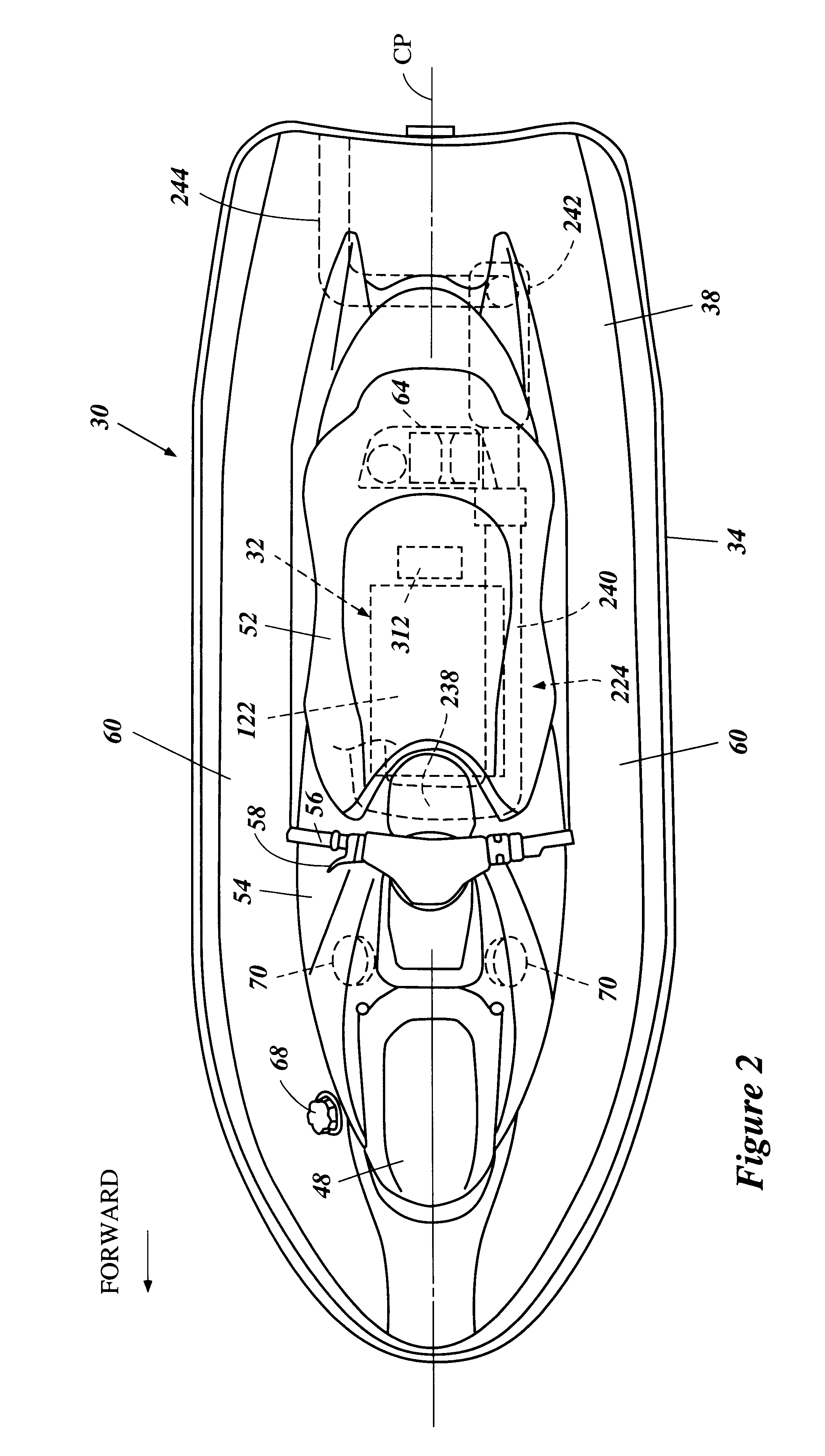
With reference to FIGS. 1 to 18, an overall configuration of a personal watercraft 30 will be described.

The watercraft 30 employs an internal combustion engine 32 configured in accordance with a preferred embodiment of the present invention. The described engine configuration has particular utility with the personal watercraft, and thus, is described in the context of the personal watercraft. The engine configuration, however, can be applied to other types of watercrafts as well, such as, for example, small jet boats.

The personal watercraft 30 includes a hull 34 formed with a lower hull section 36 and an upper hull section or deck 38. Both the hull sections 36, 38 are made of, for example, a molded fiberglass reinforced resin or a sheet molding compound. The lower hull section 36 and the upper hull section 38 are coupled together to define an internal cavity 40 (FIG. 3). A gunnel 42 defines an intersection of both the hull sections 36, 38.

With reference to FIGS. 2 and 3, the hull 34...


PUM


Abstract

An internal combustion engine, which can be disposed in a water vehicle, includes an exhaust system having features improving the performance, ease of manufacturing, and / or the water preclusive effects thereof. The exhaust system can include an exhaust manifold defining a plurality of exhaust runners and being made from at least two parts. The exhaust system can also include a plurality of individual exhaust passages extending from exhaust ports of the engine to a forward end of the engine. The exhaust system can also include an exhaust passage which extends from the exhaust ports to varying elevations relative to the exhaust ports, as well as other features.

Description

PRIORITY INFORMATIONThis invention is based on and claims priority to Japanese Patent Applications No. 2000-007571, filed Jan. 17, 2000, No. 2000-192251, filed Jun. 27, 2000 and No. 2000-204839, filed Jul. 6, 2000, the entire contents of which are hereby expressly incorporated by reference.1. Field of the InventionThis invention relates to an engine for a watercraft, and particularly to an improved exhaust system of an engine for a watercraft.2. Description of Related ArtPersonal watercraft have become very popular in recent years. This type of watercraft is quite sporting in nature and carries a rider and possibly one, two or three passengers. A relatively small hull of the personal watercraft commonly defines a riders' area above an engine compartment. An internal combustion engine frequently powers a jet propulsion unit which propels the watercraft. The engine lies within the engine compartment in front of a tunnel formed on the underside of the watercraft hull. The jet propulsio...

Claims


Application Information

Patent Timeline
Patent Type & Authority Patents(United States)
IPC IPC(8): F02B75/20F02B75/00F01N7/00F01N7/12F02B27/04F02B27/00F02B61/00F02B61/04F02B75/02F02F1/24F02B75/18F02M35/00F02M35/16F01N13/00F01N13/12
CPCF01N13/004F01N13/12F02B27/04F02B61/045F02B75/20B63B2770/00F01N2590/022F02B2075/027F02B2075/1816F02B2275/18F02F2001/245F02M35/112F02M35/167Y02T10/146B63H21/14B63H21/24B63H21/32B63B34/10Y02T10/12F01M13/0405
Inventor MASHIKO, TETSUYATAKEGAMI, MASAKI
Owner SANSHIN KOGYO CO LTD
Learn More