
Apparatus of diagnosing an internal combustion engine and a method of diagnosing of an internal combustion engine

Inactive Publication Date: 2002-10-01
HITACHI LTD
View PDF7 Cites 50 Cited by
  • Summary
  • Abstract
  • Description
  • Claims
  • Application Information

AI Technical Summary

Benefits of technology

Another object of the present invention is to provide an apparatus of diagnosing an internal combustion engine and a method of diagnosing an internal combustion engine wherein a reliability of a control unit of the internal combustion engine can be assured.

Problems solved by technology

The above stated conventional internal combustion engine apparatuses for judging a variable timing control unit for troubles have had a difficulty in judging for troubles in various modes in which the intake valve and the exhaust valve overlap condition with each other while the valve mechanism is controlled not only by the intake valve but also by the exhaust valve.

Method used


Image

  • Apparatus of diagnosing an internal combustion engine and a method of diagnosing of an internal combustion engine
  • Apparatus of diagnosing an internal combustion engine and a method of diagnosing of an internal combustion engine
  • Apparatus of diagnosing an internal combustion engine and a method of diagnosing of an internal combustion engine

Examples


first embodiment

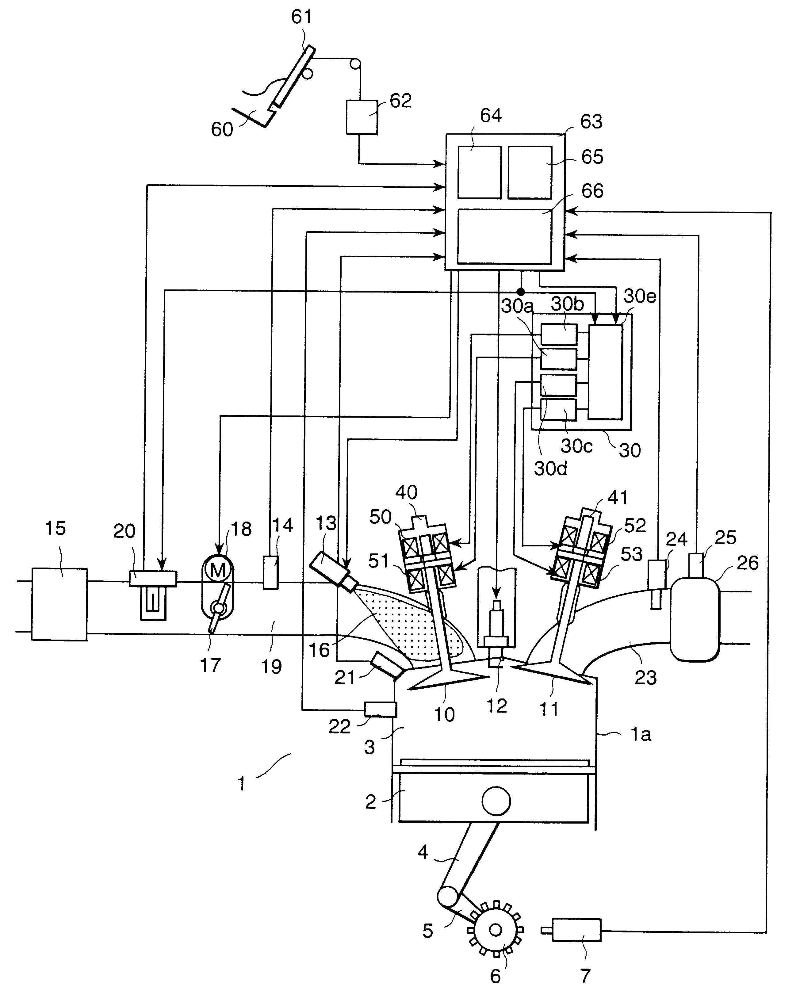
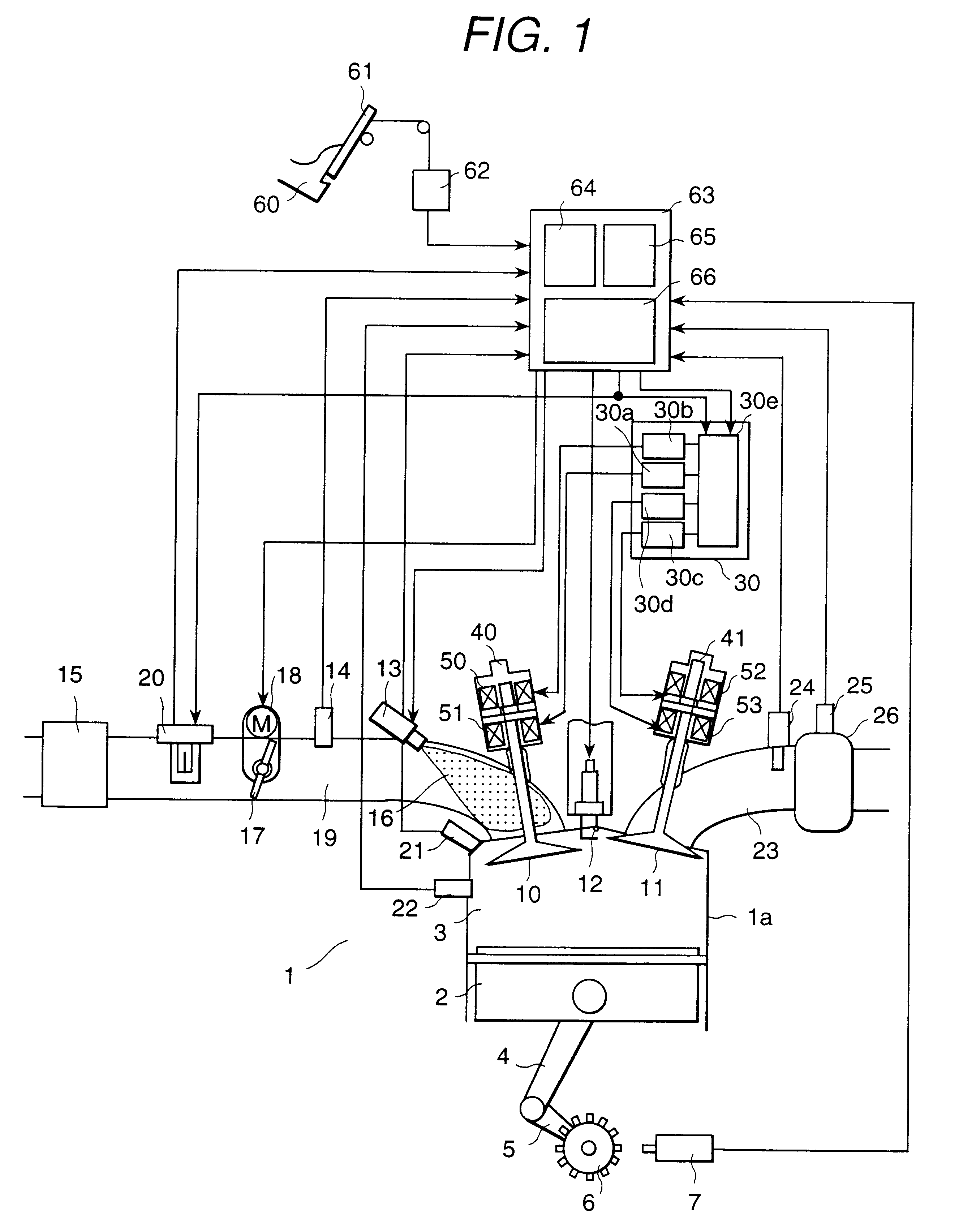
As explained above, the engine diagnosis apparatus of the first embodiment according to the present invention using the means for measuring command value signals to control intake / exhaust valve open periods and the flow rate of air flowing through the intake manifold of the engine 1 together with the direction of air flow can facilitate the diagnosis of the operating status of the valve mechanism of the engine diagnosis apparatus.

The air flow meter 20 which receives the command signal to control the opening time of the exhaust valve or the intake valve enables both measurement of an air flow rate and the diagnosis of the variable valve mechanism. It is possible to forcibly set a low output level or a high output level to indicate an abnormal status of the valve mechanism, but it is possible to provide a communication function to send both the measured air flow rate and the result of diagnosis. This engine diagnosis apparatus of this embodiment according to the present invention has ...

second embodiment

Below will be explained an apparatus of diagnosing an internal combustion engine and a method of diagnosing an internal combustion engine of a second embodiment according to the present invention referring to FIG. 13. The air flow meter 20 of this embodiment according to the present invention does not have a function to diagnose the operating status of the variable valve mechanism.

The sensor circuit connected to a power supply 201 heats a heating resistor 211 to keep it at a preset temperature and measures the flow rate of air flowing over the heating resistor 211 by sensing the quantity of heat deprived from the heating resistor 211. This sensor circuit together with the power supply circuit 203 constitutes the air flow meter 20.

The engine control unit 63 receives a signal Vin from the air flow meter 20, converts it into a digital value by the analog-to-digital converter 631 and uses the result for engine control. At the same time, the engine control unit 63 sends a control signal ...


PUM


Abstract

By employing command value signals for controlling the opening timing of an exhaust valve or an intake valve and means for measuring flow rates of an intake air of a flow direction which flows through an intake manifold of an internal combustion engine, an air flow rate corresponding to the command value signal is measured. A valve mechanism includes the intake valve and the exhaust valve for each cylinder of the internal combustion engine and is controlled by a valve control means for controlling the valve mechanism. A failure diagnosis of an operating status of the valve mechanism can be performed.

Description

1. Field of the InventionThe present invention relates to an apparatus of diagnosing an internal combustion engine and a method of diagnosing an internal combustion engine and, in particular to an apparatus of diagnosing an internal combustion engine and a method of diagnosing an internal combustion engine wherein the internal combustion engine diagnosis apparatus has a valve mechanism in which a timing of the valve mechanism has a variable timing.2. Prior ArtJapanese application patent laid-open publication No. Hei 4-91330 (1992) has disclosed an internal combustion engine apparatus for discriminating a variable timing control unit for troubles according to a difference between rotational speeds of an internal combustion engine by ON and OFF commands on a solenoid that varies the valve opening / closing timing.Japanese application patent laid-open publication No. Hei 6-317115 (1994) has disclosed another internal combustion engine apparatus for judging a variable timing control unit ...

Claims


Application Information

Patent Timeline
IPC IPC(8): F02D41/18F02D41/22F02D41/00F02D13/02F01L9/04F02D45/00F01L9/20
CPCF01L9/04F02D13/0207F02D13/0253F02D13/0261F02D41/0002F02D41/187F02D41/221F02D2041/001Y02T10/18Y02T10/42Y02T10/12Y02T10/40F01L9/20F02D45/00
Inventor KANKE, ATSUSHIOHSUGA, MINORUOHTA, KENJI
Owner HITACHI LTD
Learn More