Method for manufacturing composite bicycle frame

a composite frame and bicycle technology, applied in the field of bicycle frames, can solve the problems of corresponding frame strength loss, inability to manufacture bicycle frames according to these known processes, and inability to meet mass production, so as to avoid the extra weight and reduce the effect of strength

Inactive Publication Date: 2002-10-01
RADIUS ENG
View PDF36 Cites 30 Cited by
  • Summary
  • Abstract
  • Description
  • Claims
  • Application Information

AI Technical Summary

Benefits of technology

It is a principal object of the present invention to provide an all composite bicycle frame, wherein the entire frame or three dimensional components of the frame are lapless, thus avoiding the extra weight and strength reduction inherent in lapped construction.
The bladder is made of a heat resistant plastic that does not melt or react with or bond to the interior of the molded part. Thus, it can become separated therefrom and easily removed, along with any small residue of the foam core that may be within bladder. In the preferred embodiment of this invention, the bladder consists of a thin film, that comprises only a small volume of material. The film bladder can then be removed by pulling it out of even a small opening in the molded part. Additionally the thin film bladder itself can be a soluble plastic, preferably water soluble, such as polyvinyl alcohol (PVA) film. The use of easily soluble bladder films is advantageous where extremely small openings are used for inflation during molding and subsequent removal of the bladder. Soluble films are also used if molding of very complex features on the inside of the part might inhibit removal of the bladder. Such complexities might involve cocured metallic features inside the part.

Problems solved by technology

If the metal lugs are reduced in size to reduce weight there must be a corresponding reduction in size of the composite tubes, with corresponding loss of strength of the frame.
Since weight reduction and strength are of primary importance, the use of a combination of composite tubes metal lugs has not been entirely satisfactory.
Frames made according to these known processes are not generally amenable to mass production, primarily due to the amount of manual labor required at each stage of the manufacturing process.
Consequently, the frames are not commercially viable.
These dividing lines of overlapping composites provide weakness areas in the lugs and undesirable increased weight.
Joints between frame members are the most frequent source of structural problems occurring in bicycle frames.
This is because internal structural loads, are generally the greatest at the joints, and because it is difficult to bond the different materials at the joints.
While these frames are successful to the large extent, there are many practical concerns, and manufacturing problems relating to the complexity of forming the entire bicycle frame in one step.
However, complex three-dimensional shapes, such as lugs, one piece frames, or other large frame sections, have been formed by overlapping fiber preforms to form a lapped joint because the methods for forming tubes and the like cannot be applied to complex three-dimensional shapes.
This lapped joint not only introduces a potential weakness to the part, but requires additional material for the lap.
In addition, this lap construction method may require additional reinforcing material in the lap area, which adds more weight to the final part.
Another problem with prior-art methods for forming complex three-dimensional parts is that a preform for each mold half must be dimensioned specifically to fit into the part cavity.
This requires that each preform must be a large flat piece that when pressed into the mold cavity must distort and is likely to fold.
These folds are a source of weakness and cracks in the final part and can lead to failure of the part.
The folds can also result in resin pockets, pin-holes, and other visual and structural defects.
The constraint to shape the preform for the mold also limits the possibility of designing the preforms specifically for performance and strength.

Method used


Image

  • Method for manufacturing composite bicycle frame
  • Method for manufacturing composite bicycle frame
  • Method for manufacturing composite bicycle frame

Examples


Embodiment Construction

Comparative Discussion of the Prior-art

For some time it has been known to produce bicycle frames by interconnecting composite tubes with composite lugs. Composite lugs have been used to interconnect composite tubes and to make a entirely hollow bicycle frames. See U.S. Pat. No. 5,624,519, to Nelson, et al.

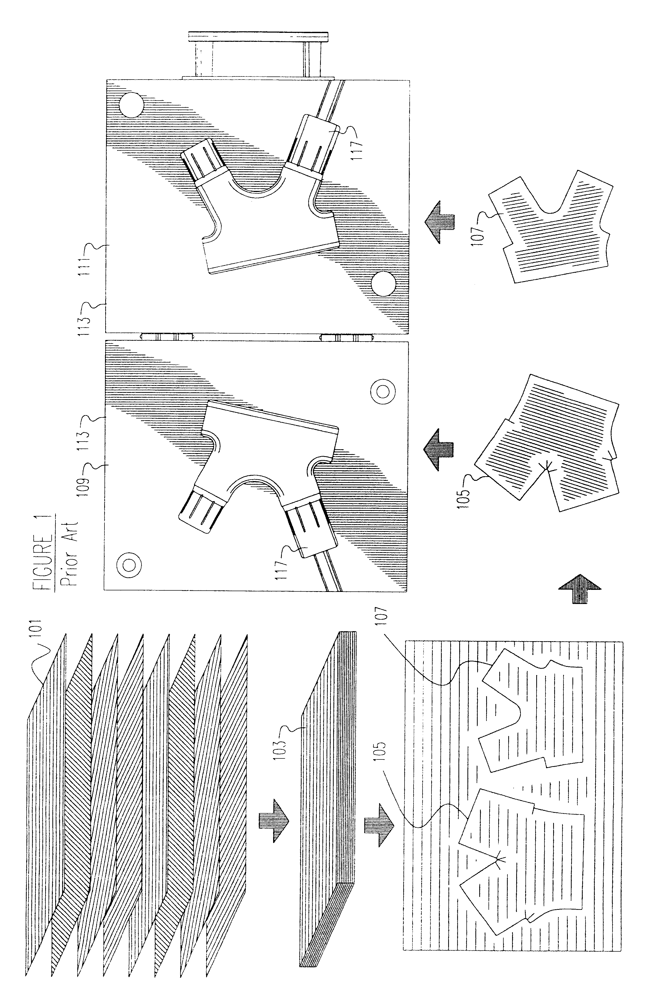
Reference is now made to FIG. 1, which is a schematic flow sheet of an illustrative prior-art method. In the prior-art, individual plies 101 of resin impregnated carbon fibers are assembled into a multi-ply stack 103. The multi-ply stack is cut to form two preforms 105, 107, which are then placed in the bottom 109 and top 111, respectively of a two-piece female mold 113.

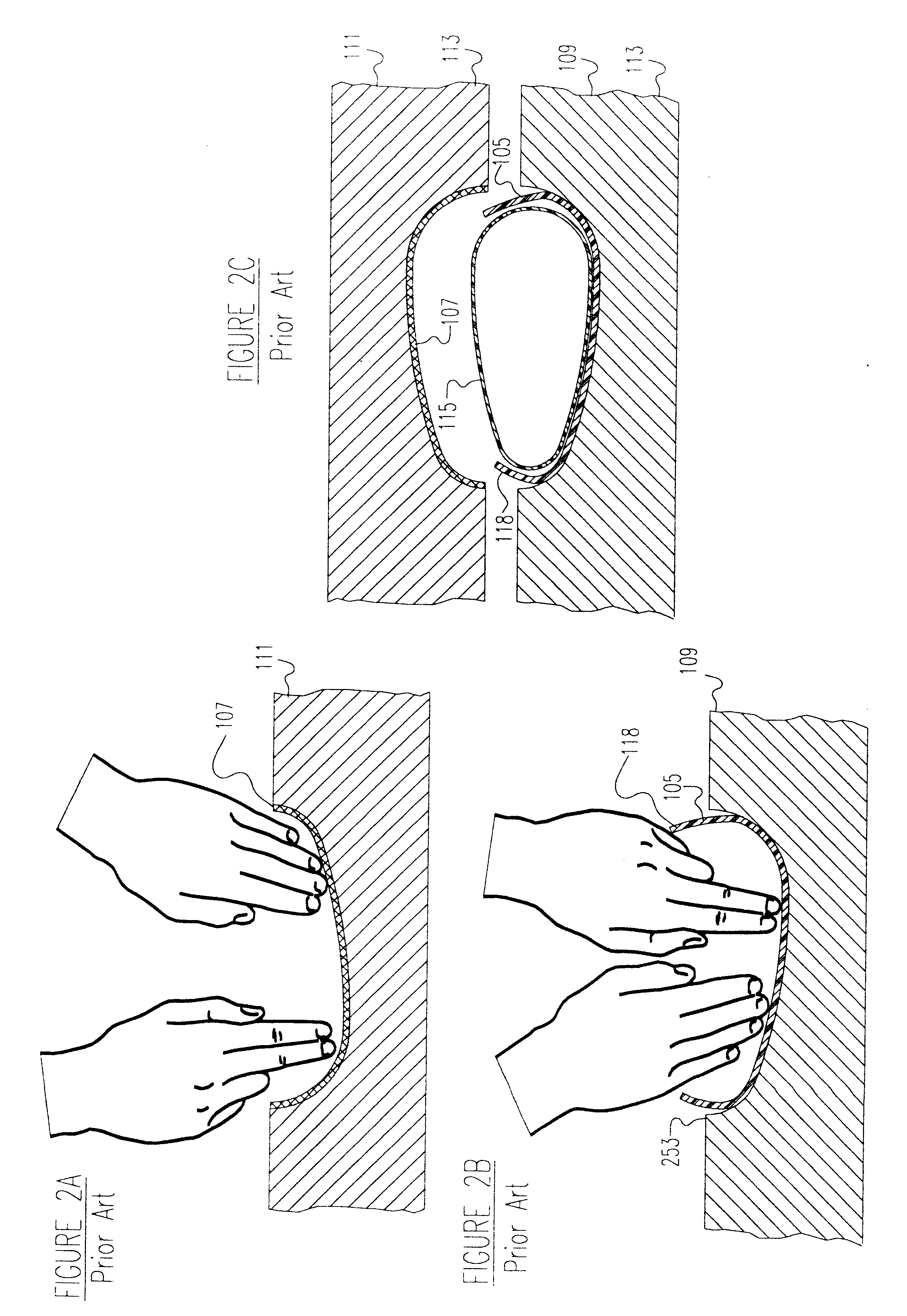
Reference is now made to FIGS. 2A, 2B and 2C. In FIG. 2A, top preform 107 comprising layers of composite material is placed in the top mold half 111. In a similar manner in FIG. 2B, bottom preform 105 comprising layers of composite material is placed in the cavity of the bottom mold half 109. Referring to FIG. 2C, a...


PUM

PropertyMeasurementUnit
lengthaaaaaaaaaa
thicknessaaaaaaaaaa
thicknessaaaaaaaaaa

Abstract

Bicycle frame components without laps made by a method comprising;shaping a fluid-removable core in the general form of the component,placing a flexible inflatable bladder around the core,wrapping over the assembly of core and bladder at least one ply of fiber impregnated with a curable resin,forming a cured part by inflating the bladder while the assembly of core, bladder, and impregnated fiber is in a mold to force the plies against the inner surfaces of the mold, such that compaction of the fiber against the mold is predominantly from the bladder inflation and not from the core, and heating to cure the resin to form a cured part,removing the bladder and the fluid-removable core from the interior of the cured part by disintegrating the fluid-removable core with a fluid sufficient to allow removal of the core and the bladder.

Description

1. Field of the InventionThis invention relates to bicycle frames. It is particularly related to light weight, very strong bicycle frames made of composite materials.2. Discussion of Prior ArtTraditional Metal Bicycle FrameBicycle frames have traditionally been constructed of assembled metal tubes. A variety of methods have been used to connect the metal tubes. The most common methods have included welding, soldering or brazing. It has also been common to use preformed metal lugs as connectors at the junctions of the metal tubes. The preformed lugs reinforce, or add strength and stiffness to the welded, soldered, or brazed joint.Bicycle Frames Utilizing Advanced Composite TubesSome modern bicycle frames utilize composite materials to increase the strength and stiffness of the frames, while reducing frame weight, relative. to traditional metal frames. Composite materials have a lower density, higher specific strength and stiffness, and better damping qualities than traditionally used...

Claims


Application Information

Patent Timeline
Patent Type & Authority Patents(United States)
IPC IPC(8): B29C33/52B29C33/40B29C70/04B29C70/44B62K19/00B62K19/16A63B53/04
CPCB29C33/40B29C33/52B29C43/18B29C70/44B62K19/16B29C70/446A63B53/04A63B2209/023Y10T428/1321B29L2031/3091B29L2031/5227Y10T428/1362Y10T428/1393
Inventor NELSON, RONALD H.MILOVICH, DIMITRIJECLARK, PAUL NORDSTROMLOUGHRY, GREGORY JOSEPH
Owner RADIUS ENG
Why Eureka
Try Eureka