
Method of filtering a fluid

Inactive Publication Date: 2002-10-08
PANASONIC CORP
View PDF17 Cites 58 Cited by
  • Summary
  • Abstract
  • Description
  • Claims
  • Application Information

AI Technical Summary

Problems solved by technology

Adoption of such a filtration system is difficult because of costs incurred in constructing and running a filtration system, thus posing an environmental problem.
Use of a CMP machine involves discharge of slurry of a considerable amount diluted with pure water, thus posing a difficulty in efficient treatment of wastewater.
Specifying the amount of chemical which attains complete reaction with objects of removal is very difficult, and hence a large mount of chemical is discharged into the wastewater, so that chemical which has not reacted with wastewater remains.
If the amount of chemical is insufficient, not all the objects of removal are coagulated and settled out, so that some of the objects of removal remain unseparated.
Hence, the thus-filtered fluid cannot be used for an application in which occurrence of a chemical reaction is to be avoided.
Therefore, if the thus-filtrated water is applied to a wafer, an undesirable chemical reaction will occur.
For this reason, the filtrated water cannot be recycled as water to be used in a dicing operation.
As a result, there is required floor space or round space measuring about 11.times.11 meters, thus rendering the scale of the entire filtration system large.
Further, some flocs float on the surface of wastewater and may flow out of the precipitation tank.
Thus, recovery of all flocs is difficult.
In short, the known filtration system suffers problems; i.e., the size of a facility, high initial costs required by the system, a difficulty in recycling water, and high running costs incurred by use of a chemical.
As mentioned above, the known filtration system suffers high running cost; specifically, electricity consumed by a motor and expenditures required for replacing the pump and the filters F with new ones.
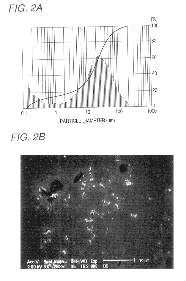
Further, the amount of wastewater discharged during a CMP operation cannot compare with that discharged during a dicing operation, and the abrasive grains mixed in a slurry are very minute and comprise grains of 0.2 .mu.m, grains of 0.1 .mu.m, and grains of 0.1 .mu.m or less.
If such fine abrasive grains are filtrated through use of a filter, the abrasive grains enter pores of the filter, thus frequently clogging the filter and making disposal of a large amount of wastewater impossible.
Eventually, the system involves enormous initial cost and running cost.
For these reasons, the known sewage treatment plant cannot be adopted.
If the second filter film is formed from only objects of removal, the second filter film is formed to have small filter pores, so that the filtration capability of the second filter film is deteriorated.

Method used


Image

  • Method of filtering a fluid
  • Method of filtering a fluid
  • Method of filtering a fluid

Examples


Embodiment Construction

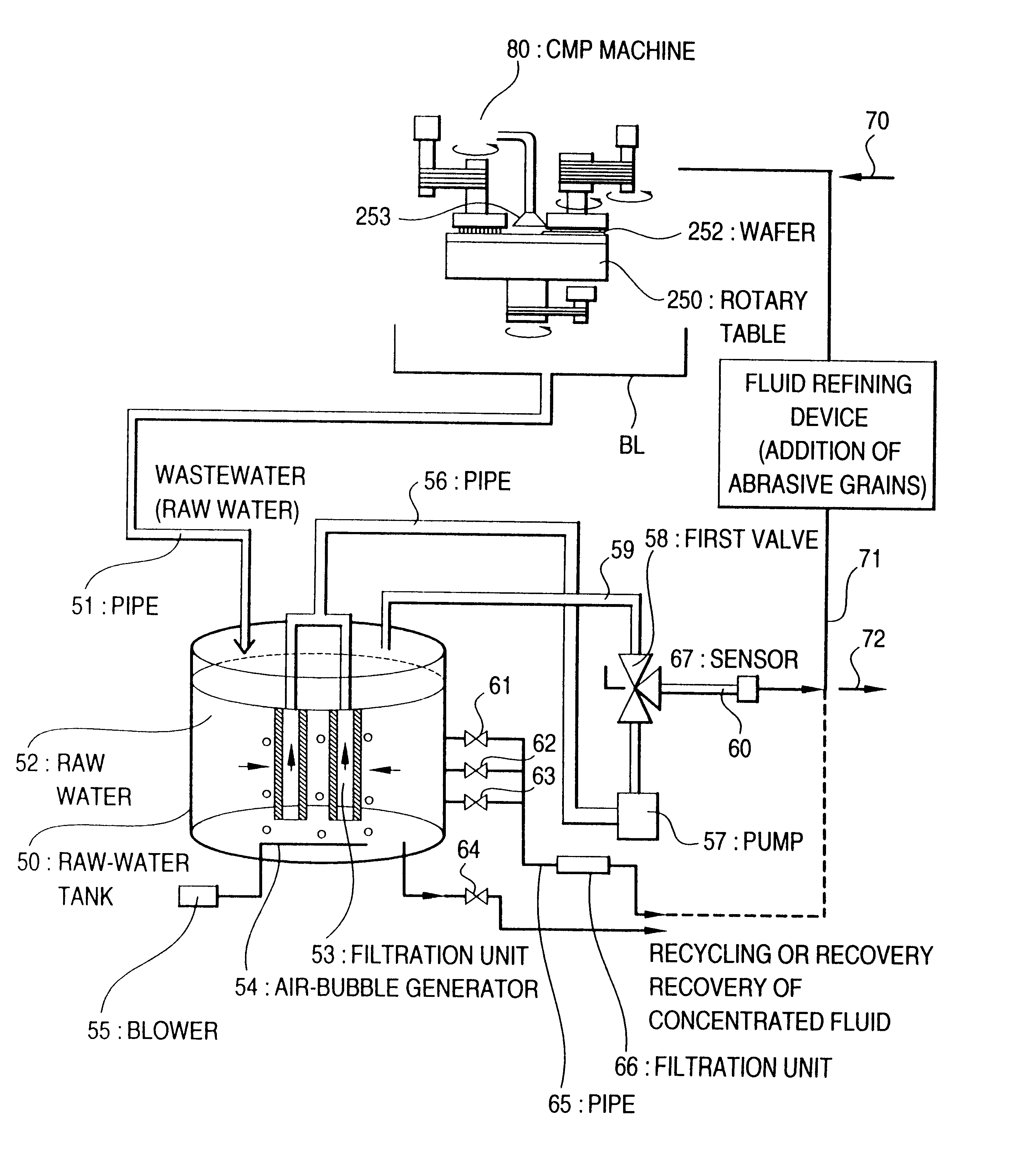
Preferred embodiments of the present invention will now be described by reference to the accompanying drawings.

In one embodiment, wastewater discharged during a semiconductor process; particularly, a dicing process, is used as a fluid. Next will be described in detail a case where dicing waste of semiconductor wafer is contained in the wastewater.

One of the features of the present invention resides in a filter. Therefore, the structure of a filter, a method of producing the filter, and the operation of the filter will now be described.

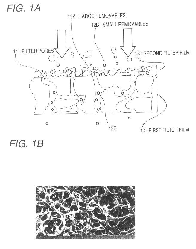
As can be seen from a schematic representation of a process for manufacturing a filter shown in FIG. 1A, dicing waste contained in wastewater is deposited on a first filter film 10 having filter pores 11, thus constituting a second filter film 13. In this way, a fine-meshed filter of superior performance is produced. A film formed over the openings of the filter pores 11 and on the surface of the first filter 10 is a cluster of solid substances 12. The...


PUM

PropertyMeasurementUnit
Linear densityaaaaaaaaaa
Timeaaaaaaaaaa
Pore sizeaaaaaaaaaa

Abstract

A fluid is filtered by first preparing a filter which includes a base filter and solid substances provided on the base filter, such that the solid substances differ from objects within the fluid to be filtered that are removed by the filter. The objects of filtration are filtered by supplying the fluid to the filter. During filtration, a force is applied to the filter to move the solid substances and objects deposited on the filter. The application of such force thus allows continuous filtration through the filter. The force can take the form of application of rising bubbles, a mechanical vibration or sonic waves to the filter. The filtration method is useful in processing fluid waste from mechanical processes, such as CMP steps.

Description

BACKGROUND OF THE ART1. Field of the InventionThe present invention relates to a method of filtering a fluid, and more particularly, to a method of removing, from a fluid, very minute objects of removal measuring 0.1 .mu.m or less.2. Description of the Related ArtAt present, diminishing the amount of industrial waste, separate collection and recycling of industrial waste, and prevention of release of industrial waste are considered to be ecologically-important topics and business issues as society moves toward the Twenty-first century. Some types of industrial waste comprise various types of fluids containing objects of removal; i.e., substances to be removed.Such fluids are known by a variety of expressions, such as sewage, drainage, and effluent. Fluids, such as water or chemicals, containing substances which are objects of removal will be hereinafter referred to as "wastewater." The objects of removal are eliminated from wastewater by means of an expensive filtration system or a ...

Claims


Application Information

Patent Timeline
IPC IPC(8): B01D36/02B01D37/00B01D36/00B01D37/02B01D63/08B01D69/00B01D69/14B01D25/12B01D29/15B01D25/164B01D29/13C02F9/00C02F1/44H01L21/00C02F1/32C02F1/52B01D24/00B24B55/12B01D61/14B01D65/02B01D71/02B01D71/26H01L21/304
CPCB01D25/164B01D29/15B01D36/02B01D37/02B01D63/082B01D69/14C02F1/444H01L21/67028B01D29/39B01D29/58B01D29/56B01D29/52B01D29/70B01D29/86B01D36/04B01D37/04C02F1/32C02F1/441C02F1/52C02F2103/02C02F2103/346C02F1/44H01L21/304B01D61/14B01D24/00B01D63/0822B01D63/0821
Inventor TSUIHIJI, MOTOYUKIIINUMA, HIROFUMI
Owner PANASONIC CORP
Learn More